Introduction: How to Convert AC to DC


This tutorial shows how to convert AC current into DC current. This tutorial will teach you what a transformer, diode and what a bridge rectifier is. Warning I am not responsible if you hurt yourself, use common sense and research a little to know what your doing! Let's get started!
Step 1: What's a Transformer

A transformer is a electrical device that changes electricity into a magnetic field, then back to electricity. This will allow a transformer to transform voltage or take out ground loops. There are isolator transformers, step up transformers, and step down transformers. Isolator transformers isolate the negative voltage from DC current and audio signals. It is used in ground loop isolator . A step down transformer, steps down voltage to a allowable voltage, kind of like a phone charger or power supply. A step up transformer on the other hand steps up voltage to a allowable voltage, kind of like a NST transformer ( Neon Sign Transformer) or car ignition coils to make the Sparks at the spark plugs.
Step 2: How to Wire a Transformer

Ok, bought or salvaged a transformer? For a basic transformer like the ones at RadioShack, for step down transformers there are 2 big wires and 2 or 3 small wires. You can get a plug and wires or cut off a plug off a power strip Etc. The big wires are for the wall socket and the small wires are the output. Strip the 2 or 3 wires and cut the green wire. Solder the plug securely to the transformer and insulate it properly with heat shrink or electrical tape. Now plug in your transformer and if nothing blows up then congratulations you got a working transformer!
Step 3: Converting AC to DC Materials
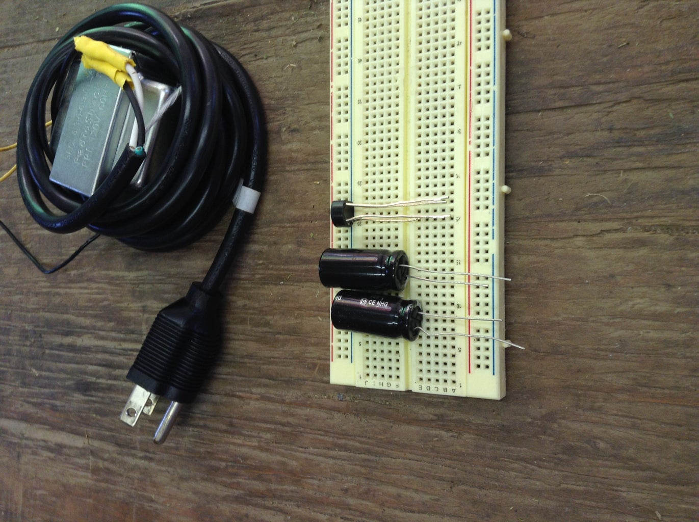
Converting AC to DC is not hard. You will need the following materials.
1 transformer
4 silicon or rectifier diodes( or just buy a rectifier)
1000uf and up capacitors
That's it that's pretty easy.
1 transformer
4 silicon or rectifier diodes( or just buy a rectifier)
1000uf and up capacitors
That's it that's pretty easy.
Step 4: Converting AC to DC
Are you ready to convert AC to DC! Once you get your materials your ready. Look at the diagrams and schematic to guide you through. If you don't understand the schematic paper, then look at the other circuit diagram by fritzing. I drew a diagram of what happens to the wave forms when it passes through each component. First the AC current is a sine wave that dips in and out between negative and positive. When it passes through the rectifier or diodes it outputs the positive half of the wave form, it is technically DC but its not. But when it then passes through the capacitors, it outputs a steady voltage.

Step 5: Closing
I hope this project worked out for you and if you have trouble comment and I will help you out,


