
During the termination process, connectors must be cleaved before they can be polished and laser cleaving increases production yield and connector performance.
Laser Cleaving (integrated denubbing and epoxy removal) has been considered a solution by several to problems with operator and tool-dependent mechanical cleaving issues, epoxy bead size, overuse of consumables in polishing and connector challenges.
Part of the solution found with laser based cleaving systems is the elimination of multiple manual steps in the connector terminating process. The combination of cleaving, denubbing and epoxy removal into one laser processing based step has been a big change for the industry.
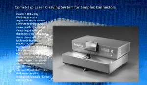
Fiber Optic Center will be performing demonstrations at ECOC this month with the Comet-Ssp Single Step Polish Laser Cleaving System. The connector is placed into the Comet™ machine and a focused C02 laser beam is automatically scanned across the connector end face removing both the fiber stub and epoxy bead in one quick step. FOC is making appointments for this demo and also welcoming booth walk-ups to discuss this solution to end face quality reworks, core cracks and chip outs elimination and improved working conditions with challenging fiber types.
For those unable to attend ECOC 2015 this month, there is demo video on the FOC website (VIDEO) and the new AskFOC email tool for questions prior to the show (AskFOC@focenter.com).
For more information on Single Step Polishing After Laser Cleaving, please visit our article published in NASA Tech Briefs and parts of the article can be seen here:
Single Step Polishing After Laser Cleaving
With the standardization of 4G wireless, the increase in cloud storage and computing, and the push for faster network data rates, the highest quality passive interconnect systems must be used. While the robustness and size of these interconnections, fiber types, and cable management all play major roles in the backbone, what happens at the tip of the connector also greatly affects the optical performance of the system.
To start, high-quality connectors with tight tolerance ferrule holes, both in size and concentricity, must be used. Connector termination involves several processing steps. Each of these steps has its own processing concerns.
With cable preparation, it’s important that the fiber is not damaged during stripping. Fiber chips will cause optical loss. While the connector is installed, the proper amount of epoxy and the correct cure schedule is critical. Too much epoxy and the spring will lock up; too little and voids will form. If the correct temperature isn’t met for the proper amount of time, the epoxy will not fully cure. In both cases, the longevity of the connector will be marginalized.
After cable preparation, connector installation and crimping, and epoxy curing, the end face needs to be processed. The steps include cleaving (also called scribe and break) and polishing. Cleaving and polishing bring the connector to the required specifications. A flaw in any of these steps may cause a yield problem. These steps also have an impact on the steps that follow, and may contribute to problems further down the termination process.
Standard polishing for single fiber connectors typically consists of three to five polishing steps, starting with relatively rough epoxy removal grit and gradually going to a final lapping film, which can be .02 um. Some of the middle steps use relatively costly diamond films, which are used multiple times to minimize the CoC (“Cost of Consumables”) per connector.
The Challenge with Fiber Cleaving
The industry is continually looking for ways to increase yield, decrease CoC and labor expense. Reducing the number of polishing steps helps. CoC goes down, yield goes up, labor cost goes down, and less equipment and equipment maintenance are required. There is a clear way to get there.
Traditionally, cleaving is done using a scribe tool with a sapphire, ruby or carbide tip. A careful operator has to scribe the fiber just above the cured epoxy and gently pull the tip of the fiber parallel to the fiber axis without producing a crack. When not done properly, this resulting crack often makes the termination. This operator has to be one of the more careful and conscientious people in the factory, and does the same repetitive job all shift. If a crack does result from the scribing procedure, the connector needs to be cut off and the entire process needs to be redone. On breakout cables with many fibers, this creates other problems. If breakouts are at precise lengths, all ends would need to be redone.
After the cleave, a manual denubbing process takes place to take the fiber stub down to the epoxy, so it doesn’t crack during the epoxy removal step. This is time consuming and very operator dependent. The connector end face can also be deformed if it isn’t done properly and it won’t be detected until testing. With the manual cleave, traditional machine polishing requires four to five steps using silicon carbide, diamond and silicon dioxide lapping films with rubber pads after the denubbing – epoxy removal, multiple geometry end face forming, and the final – to reform the geometry of the connector.
Before connectors are terminated, when they are purchased, they come in with the correct geometry, radius of curvature, and apex offset. With traditional manual cleaving, the connector end face is being destroyed during the epoxy removal step and has to be reformed.
The Solution
A new cleaving technique, using a CO2 laser, largely automates the process. The operator simply places the connector into the laser cleaver, the laser scans across the fiber and epoxy bead, and it cleaves both together. The human factor is eliminated from the cleaving and denubbing steps.
Laser cleaving was introduced a few years ago, but a recent development produces even more savings in the termination process. Earlier laser cleaving models cleaved 70 um from the ferrule pedestal; the newer design can cleave as close as 35 um from the pedestal. The consequence of this improvement cuts the required polishing steps from three or four to only one step, using the final polish film. Because assembly manufacturers typically use pre-radiused 2.5 mm ferrules, and the new SSP laser cleaving leaves a very short fiber stinger, about 35 um, with an epoxy layer as thin as 10 um, polishing can be completed with only final film. Even 1.25 mm ferrules, which are not typically pre-radiused, can be polished with only the final film since the polished diameter is relatively small. Developments are also being done with 1.6 mm and 2.00 mm military and commercial pins and sockets.
This process results in a connector with tightly controlled geometry, a very high yield, lower CoC, and shorter labor time. Pencil tip 1.25 mm ferrules and 2.5 mm ferrules with relatively small pedestals, can also get polished with only one polishing step after the laser cleaving. Final lapping film has the capability to remove the residual epoxy layer, provide the specified Radius of Curvature (ROC), and control the fiber height (protrusion or undercut) within the desired specification to meet customer demands.
By decreasing the number of polishing steps, the cost per connector will go down. By relying on the connectors’ incoming ROC and removing all cracks due to cleaves, yields should also improve.
Note: In a production environment, there may be a requirement to perform a very brief silicon carbide polishing step to remove the epoxy residue before the final film. This also helps extend the life of the final film.
Next Steps
Most 2.5 mm ferrules used by assembly manufacturers are preprocessed with an ROC of 15 to 25 mm. This ROC reduces the polishing time after traditional hand cleaving. This ROC range is too wide for many terminated connectors. The ROC distribution of incoming ferrules is too wide for the needed finished termination. With 1.25 mm ferrules, the situation is slightly different. Many assembly manufacturers use incoming ferrules with flat pedestals, as opposed to pre-radiused. To take full advantage of laser cleaving and minimize polishing as much as possible, it may help to specify incoming ferrules within the mid-range of the final connector spec, and with tighter tolerance.
The full article with graphics can be read at: http://www.techbriefs.com/component/content/article/ntb/features/22094
Additional resources from the FOC team include:
- Category Resources:
- View the Glossary, Acronyms, Military Specifications for Connectors
- Q&A Resource: email technical questions to AskFOC@focenter.com
Have questions about this article?
Contact FOC with questions at: (800) 473-4237 / 508-992-6464 or email: FiberOpticCenter@focenter.com and we will respond ASAP.