- Home
- Product Categories
- Data Loggers
- SparkFun OpenLog

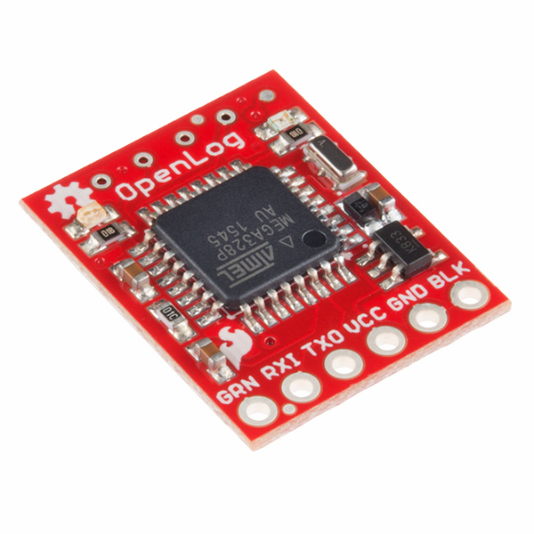
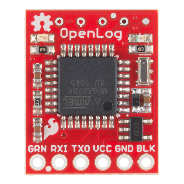
SparkFun OpenLog
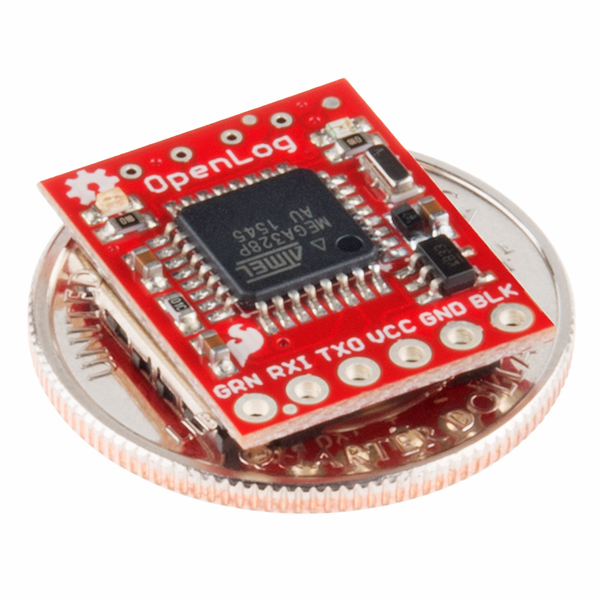
The SparkFun OpenLog is an open source data logger that works over a simple serial connection and supports microSD cards up to 32GB. The OpenLog can store or "log" huge amounts of serial data and act as a black box of sorts to store all the serial data that your project generates, for scientific or debugging purposes.
The SparkFun OpenLog uses an ATmega328 running at 16MHz thanks to the onboard resonator. The OpenLog draws approximately 2-3mA in idle (nothing to record) mode. During a full record OpenLog can draw 10 to 20mA depending on the microSD card being used.
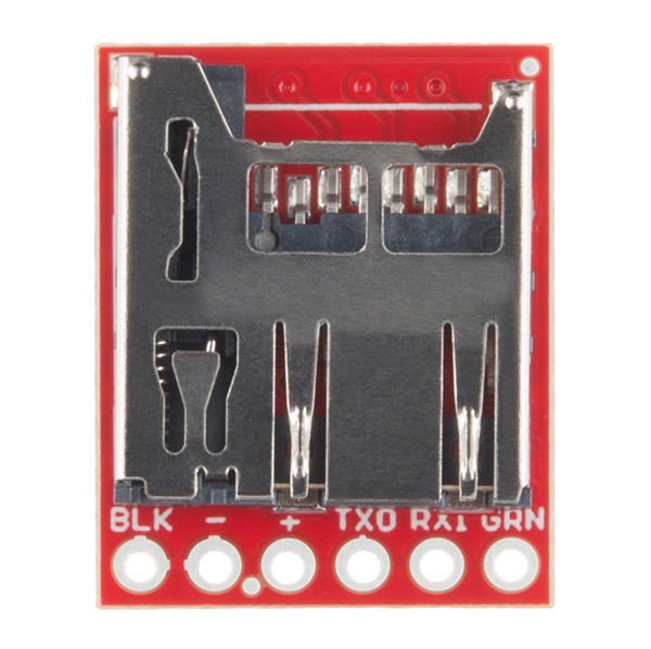
All data logged by the OpenLog is stored on the microSD card. Any 512MB to 32GB microSD card should work. OpenLog supports both FAT16 and FAT32 SD formats.
For even better performance the OpenLog Artemis is the tool you need, featuring logging speeds up to 500000bps.
- VCC Input: 3.3V-12V (Recommended 3.3V-5V)
- Log to low-cost microSD FAT16/32 cards up to 32GB
- Simple command interface
- Configurable baud rates (up to 115200bps)
- Preprogrammed ATmega328 and bootloader
- Four SPI pogo pins
- Two LEDs indicate writing status
- 2mA idle, 6mA at maximum recording rate
SparkFun OpenLog Product Help and Resources
Choosing an Arduino for Your Project
December 11, 2017
Examining the diverse world of Arduino boards and understanding the differences between them before choosing one for a project.
micro:climate Kit Experiment Guide
July 21, 2017
A weather station kit that is built on top of the inexpensive, easy-to-use micro:bit and Microsoft MakeCode.
Core Skill: Soldering
This skill defines how difficult the soldering is on a particular product. It might be a couple simple solder joints, or require special reflow tools.
Skill Level: Noob - Some basic soldering is required, but it is limited to a just a few pins, basic through-hole soldering, and couple (if any) polarized components. A basic soldering iron is all you should need.
See all skill levels
Core Skill: Programming
If a board needs code or communicates somehow, you're going to need to know how to program or interface with it. The programming skill is all about communication and code.
Skill Level: Rookie - You will need a better fundamental understand of what code is, and how it works. You will be using beginner-level software and development tools like Arduino. You will be dealing directly with code, but numerous examples and libraries are available. Sensors or shields will communicate with serial or TTL.
See all skill levels
Core Skill: Electrical Prototyping
If it requires power, you need to know how much, what all the pins do, and how to hook it up. You may need to reference datasheets, schematics, and know the ins and outs of electronics.
Skill Level: Rookie - You may be required to know a bit more about the component, such as orientation, or how to hook it up, in addition to power requirements. You will need to understand polarized components.
See all skill levels
Comments
Looking for answers to technical questions?
We welcome your comments and suggestions below. However, if you are looking for solutions to technical questions please see our Technical Assistance page.
Customer Reviews
4.2 out of 5
Based on 22 ratings:
4 of 4 found this helpful:
Great functionality but two broke immediately
Purchased two for research project. Wired them up to device and worked perfect with stock firmware. After two-three insert/ejections of the microsd card the mount failed to hold the card. When you insert the card it just springs right out. Rewired a second one up and had the same thing happen. Both units worthless. After inspection there is a tiny hooked wire that rides in a plastic groove to lock and unlock the microsd card. The plastic is so soft that after a couple of inserts the groove no longer functions properly.
1 of 1 found this helpful:
Suggestion for future OpenLogs when used without microprocessor.
I use OpenLogs with GPS modules. No microprocessor. It sure would be nice if there was a clock inside that would name the files by their date. There's a 3 volt power supply chip on it. Can you make that a little easier to get at so we can power 3 volt things from it. Mechanically, there's no good way to mount the thing with double sticky. The flattest part of the device has springs which retain the SD card. Double sticky there is a problem.
3 of 3 found this helpful:
Just what the doctor ordered
I had been having some intermittent connection problems with a custom esp8266-based board. Devices that were further out from a router would sometimes lose their connection, reset, but then fail to reconnect. I had no way to capture debugging logs while deployed and very limited I/O to add anything else to the board for this purpose.
The OpenLog really fit the bill nicely here. It could reuse the serial TX/RX lines while deployed, so all I had to do was find a reset line. After some trial and error, I found resetting the OpenLog at esp init time was essential for stable operation. In addition, I added some code to check to see if the OpenLog is plugged in and to set the baud rate appropriately, 9600 w/ OpenLog, 115200 for console.
I'm very happy with what I ended up with. $15 for OpenLog, $6 for an SD card, and now I can get logs while the system is deployed.
2 of 2 found this helpful:
OpenLog is a powerful tool for embedded controllers
One of the best modules I ever used. It has all the good features, small, large capacity, simple interface, low price, great documentation, low power, and open source. Need to be considerate of data rate for the higher speed applications. Highly recommend for any data storage project. Worked first time following Sparkfun great hookup guide.
1 of 1 found this helpful:
Pretty darn useful and simple
- RTFM - read the flipping manual - really - once read and understood, it's a doddle to setup and run. I have 3 - all logging away merrily. Next step is to interpose switches inbetween the Rx / Tx pins of say an Arduino UNO to access remotely (a) data from the OPENLOG (b) also arduino to download program mods.
1 of 1 found this helpful:
Great for recording GPS signals in small RC airplane and drone.
Doing a perfect job of recording the outputs of several different small GPS receivers and weighs so little that it doesn't load airplane very much.
I have a complaint. The unit has far more capability than is in .config file when delivered and a reference to a simple setup program would sure be welcome.
1 of 1 found this helpful:
Very cool to log GPS data
Very simple to setup out of the box. I connected to GPS-13740 GPS Receiver - GP-20U7. I got the idea from instructibles.com and so for just over $35 for GPS and logger I have a cool GPS Logger. I can upload the data to Google Earth and see a visual track of where it's been. Fun for boating, hiking, etc.
1 of 2 found this helpful:
Nice SD card reader/writer, software weak
This is a great little SD card reader/writer. The sample code software is very sparse. I had to write much more elaborate code to make this logger useable and it took some time and experimentation to get it right.
Works well except the spring seems weak
I'm agreeing with review by Member #670407. We use this component in a couple different devices and when you take the SD card out more than a few times and aren't extremely gentle, the spring seems to break. Would love to see a rev that makes it more hardy. Thank you.
The easiest way to add SD card capability!
I bought mine to use in a museum ticket printer. The printer not only prints tickets it keeps track of the number and type of visitors to the museum and stores the data and the card. I used a pickax processor, and had no problems at all.
Great little device!
I am building a research payload for a community called ANSR of which I am a member. This devices works with no problem with the BASIC Stamp Microcontroller I use to record sensor data. Overall, never had any problems to this date and is extremely easy to use.
Best thing to add to any microcontroller project!
Easy to use and it just works! Also, you can program it like an arduino pro mini; I just wish it had a couple of DIO pins broken out (in addition to tx and rx).
solid logger
I was able to reliably log a stream of approx. 20 chars/record at 200 recs/sec using 57.6k interface. Using arduino pro mini. Very handy!
So useful and so easy
I have used this in several professional test situations, and it hasn't let me down. You can just connect and go, or with some more involved commanding you can take advantage of the file operations to organize your data as you collect it. The only thing that I struggled with is the fact that the command mode needs carriage returns rather than line feeds, which caused me several hours of flailing before I could get the file operations to work. It would be nice if that were configurable in the micro-SD config file.
Very useful and simple to use!
I connected this device to a simple 3.3V uart on a mobile device I am testing. My device had a wire supplying 3.3V so the installation was a snap. It works simply - just put in a microSD card and the OpenLog will create a "config.txt" file. Edit this file on the card using a computer to set the baud rate for your device. This allowed me to remotely capture days of serial logs from my test device. Note that microSD cards >16GB capacity are not easily formatted in the necessary FAT32 file type. But 16GB is a lot of capacity for my application.
Great for Small Projects
I needed a way to log data from a series of tests in a lab that cannot use a PC/laptop. I tried for a month to get Chan's FatFS USB stack to work without any success. Then I found this. Great little module.
2 things I recommend to Sparkfun engineers:
1 - Make a copy of this that allows data to be logged to USB thumb drive.
2 - update design to use normal SD card rather than these ridiculously small micro sd cards.
Works well with Micro:bit and Weather:bit
Easy to use and this page gives instructions: https://learn.sparkfun.com/tutorials/microclimate-kit-experiment-guide/experiment-7-logging-to-the-microsd-card
(Please note that the code on the page does not correspond to the text on the page. There is no Press Button A and the display is blank.) I added a "show string row" line so the display would show something and you can tell it's working.
Works well as a logger, or file manager, not both
No trouble getting the logger up and running with command mode off, which is what I needed, bare bones data logging. However it would have been really nice to be able to do file management with the same code, but switching between reading and writing is not supported, or at least there's not a clear way to accomplish it. On the next OpenLog version there should be a PIN or other means to toggle the functionality.
Works as it should
I've only played with this enough to get it going to know that it works with my micro:bit .
0 of 1 found this helpful:
Great idea ...
I love this idea ...
In it's current form it has a 1000 and one uses ... but I wish there was a version with a barrel power connector and DB9 male connector.
Fantastic for logging to micro SD cards!
I have tried the SPI based adapters, not nearly as useful as these. The SPI stuff is cheaper but they have speed limitations and must be buffered and carefully managed to avoid data loss.
The OpenLog is so simple, just connect it to your serial port and forget about it.
I've found that you can stream error free continuously at 57,600 baud with a class 10 card (10 MB/s), and 115,200 baud error free with a class 30 or v30 card (30 MB/s). Since I normally like to run my serial monitor at the latter rate, that is perfect for what I need.
Plus this only takes one IO pin (serial TX) vs. four for SPI, and the adapter is about the size of a postage stamp. Level shifting is optional, only needed for reads but should really work fine without it (plus I don't do reads anyway, do that later from my laptop).
I plan on putting an OpenLog on all my bots from now on. =)
I don't use arduino. I have PICs. Can anyone tell me what the GRN and BLK lines go to? I assume that GRN is some sort of reset and BLK is just another ground pin, but the schematics I've seen are not clear on this.
Note that if you look on the two sides of the OpenLog PCB, you will see that some of the pads labeled by alternative sets of labels. E.g. the pad for supplying the board with it's connection to the grounds elsewhere (of power supply, of connected host (e.g. Arduino) is labeled "-" on one side, "GND" on the other.
In similar news... be careful that you don't mis-read GRN for GND or vice versa. (The GRN pad, as M-Short noted, is connected to the reset of the AtMega328 at the heart of the OpenLog.)
The GRN and BLK labels on our boards actually stand for green and black since those are the colors of the outer wires on the FTDI cable. A lot of our boards will have that standard 6 pin header even though all 6 pins are rarely used. The GRN label is the DTR pin and goes through a capacitor to the reset pin of the ATMega328. The BLK label is GND.
It would be nice to see more of a "traditional" datasheet created for the device. It is nice having the hookup guide IF I want to hook it up with an FTDI basic in a hobbyist sense, but I'm trying to use this in an entirely separate environment. So something with standard datasheet sections such as:
Pins: Which are in, which are out, what do they do? I don't want to have to learn about an FTDI Basic to figure out how to use this. Electrical characteristics: Normal behavior. What about input power supply voltage vs. dropout of the on-board regulator? Will it run if supplied with 3.3V? Absolute maximums: Probably just some basic repeating of the micro and SD parameters - probably 3.6V max. Dimensional drawing.
Bought the old OpenLog (DEV-09530), ages ago. Looked Great! When I FINALLY got around to trying to try it out (!), I found the new documentation overwhelming. Great to have all those features, but I just want to walk before I run, use it in the simple way that the (current) OpenLog wiki says it can. And "need" to know if the simple things I think I can do with the 09530 will still work if I need more, and by the replacement.
A few questions arise, though... all of this in the context of simple use. Data lines... a) The old documentation said 3v3 or 5v acceptable. Present doc only mentions 3v3. Is the DEV-13712 really a 3v3 only device? b) Is sending data to the TXI input of the OpenLog "enough"? Do I NEED to connect to DTR, or the OpenLog's TX0 output?
And... c) Default data rate: Still 9600? d) Can the new device still manage, however crudely, to create new files "by itself" at each reboot?
The "basic" is really all I needed, wanted. As I say: Congratulations on all that the OpenLog can now ALSO do... but I'm not ready for that. I just wanted what the old one was said to be able to do.
(I have some of the old, DEV-09530's. These questions primarily about using one of them. If, say, the 09530 can accept a 5v input, but the DEV-13712 can only tolerate 3v3, please be clear about that (and other) differences? (Apart, of course, from the fact that the 13712 can do MORE than the -09530 could))
P.S. Greatly encouraged by Nate's helpful reply below, I went further with my OpenLog, and along the way generated a "Simple use- an intro" webpage... http://www.arunet.co.uk/tkboyd/ec/ec3openlog-intro.htm
To be clear, you can power OpenLog at 3.3V or 5V.
a) We're conservative with our documentation. The ATmega runs at 3.3V so if you power the OpenLog at 5V and transmit a 5V signal into the OpenLog it will activate the internal clamping diodes inside the ATmega328 (pulling the signal down to 3.3V). I've had a few dozen OpenLogs in the field receiving 5V from an Uno for nearly a decade without failure (it's fine). If you're worried, put a 220 or 1k resistor inline from the Arduino's TX pin to the OpenLog's RX pin; this will reduce the current flowing into the clamping diode. If you're really worried, checkout out Bobby's recommendations here.
b) You need three connections on the OpenLog: 5V, GND, and RXI. No DTR or TXO.
c) Yep
d) Yep - that's the default action
I've noticed that the description of this product lists the draw as being 2-6mA. The draw should be 2-6mA at Idle and 20-23mA when writing, as shown in the hookup guide.
Thanks for pointing that out. I've updated the description.
I have to assume from a brief overview that this does not timestamp. If this true and also I take it the software for this is the same for the arduino environment? So it shouldn't be too much to add this in theory right?
Correct. The OpenLog does not intrinsically stamp files, just sequential (LOG00057, LOG00058, etc).
In the past I have pulled in GPS date/time, put it in the log, and then python'd my way back to dates on the files.
Is this device available in the eagle library so that I can match the footprint on one of my boards I am making?
Do we need the DTR cable connected?
Can I just hook power and TX/RX?
You just need power and TX/RX, we put the full FTDI header footprint to make it easier to connect things with matching FTDI footprints.
And if you only want to write to the device, then you don't need the data line for data from the OpenLog to the Arduino (or whatever source of serial data you are using.)
Hi, anyone has used write Offset command? I haven't found a piece of sample code using this function. and can't make it work. regards!
Most reviews say this is an instant-gratification, plugNplay device. However, I have not been able to get mine to do anything but blink its blue LED (three blinks, pause, three blinks). None of the sample sketches get past the "is serial available" test; it does not create a CONFIG.TXT file on boot. Should I assume I have a defective unit? Been banging my head on it for a day or two now with no results. Every other Arduino device/library I have tested has worked, so I don't think it's my Uno or my brain that is broken (although the latter is always a possibility!). The SD card I am using has been formatted FAT (OSX Disk Utility) and mounts, reads and writes correctly under OSX.
PS another test: "If you get OpenLog stuck into an unknown baudrate, there is a safety mechanism built-in. Tie the RX pin to ground and power up OpenLog. You should see the LEDs blink back and forth for 2 seconds, then blink in unison." When I do this, the LEDs blink rapidly back and forth for about 2 seconds, then only the green LED stays on. There is no blinking in unison. Is my unit broken?
Three blinks, pause, three blinks is the SD init error. Try formatting your SD card on a computer. It could be that one of the solder connections on the microSD socket is bad - this is really rare and I haven't seen it in 6 years but it did happen once back when we were dialing in the reflow profile on the socket.
It really should be plug and play. Sorry you're having issues. Feel free to contact us if you continue to run into problems. We don't want anyone to beat their head against a wall.
Hi Nate, thanks for responding! I edited my post, possibly after you read it. Note SD card was formatted FAT and is readable/writable on a desktop computer... also final paragraph as it now reads: device is not going through the baud rate reset procedure as described. It responds to grounding Rx, but only halfway. Back-n-forth blinking yes but there is no synchronous blinking afterwards. There is also no "Morse O blink" of the blue LED after the baud rate reset (presumably) fails.
I did contact my retailer to ask if the part is a dud and would they exchange it, but they want me to re-flash the device... and that means buying yet more parts (FTDI and -- maybe -- a crossover board?). The instructions for reflashing are quite daunting for a newbie. I think I'm getting in over my depth here... it could take a couple of weeks to get this working what with shipping and so on.
So far, I have to admit to not being very happy :-( I thought it would be super easy and I could get on with my real telemetry project, but it seems I have to take on a whole additional project with more parts and more complicated procedures just to get the OL working.
I "only" wanted.. for a starting point, anyway, the "plug n play" logging device... and it worked out of the box for me. (Well, admittedly, it only worked the SECOND time I tried to run by sketch, which was a great relief because the reason it didn't run the first time was that I had the Vcc and Data (From Arduino to OpenLog) wires connected up reversed.) Details of the Really Really Simple use of OpenLog at http://www.arunet.co.uk/tkboyd/ec/ec3openlog-intro.htm
Hey, this is great, but if you decide to upgrade it, consider breaking out a couple of DIO pins; I like to reprogram mine, and having just two pins would be sooo handy.
Are there any plans to make a version of this that uses a full sized SD card instead of this micro sd?
Not at this time. Part of the power of OpenLog is minuteness.
Why do you want a full sized SD card? More storage space for cheaper? A 4GB microSD will allow you to log for...
4,000,000,000 bytes = 32,000,000,000 bits / 9600bps = 3,333,333s = 55,555min = 925 hours = 38.6 days
38.6 days straight before you really run into capacity problems.
Is it possible to record video using OpenLog? I have one and want to use it to record videos and or pictures. Is there a way to do this? In all the examples that I have seen, it is only used to record characters.
Probably not. Really the OpenLog is an Arduino with a uSD card slot so you can program it to take different data on those pins and save it to the uSD card. As for video or pictures that depends on the source. Based on the fact that commercial video recorders and cameras already have storage slots I'm guessing you are going with a bare camera. We do have cameras that output data over serial and you could probably use this although you'd likely need to modify to firmware to correctly close out a file at the right time. Really it is hard to say without knowing anything about your source. If you have any other questions feel free to contact our techsupport team.
I am using your CMOS camera module; so the output is RCA.
That module outputs NTSC which does 29.97 interlaced frames per second each with 525 scan lines. If you modify the OpenLog to just save every bit (you will need to figure out the timing for each bit) you can save it and read it back with something that takes NTSC. I'd double check to make sure the Arduino chip can read at that frequency with enough free clock time to also write. It is one of those things that is likely technically possible, but as this is well outside of the intended scope of the board you would basically need to rewrite the firmware to meet your needs. I'd look for something that is designed to read an NTSC signal and convert it to a more usable format (like mp4).
obtained 20 pcbs of a weird variation of these as a ding & dent product. what i mean by weird variation is that the ones i have are different by appearance... strange...
I was wondering if you could shed some light on the pins for Proteus' microSD card package. I'm looking at the MicroSD card as given in this schematic: https://cdn.sparkfun.com/datasheets/Dev/Arduino/Boards/OpenLog_v15.pdf and am having trouble correlating the pins to the package as given by the microSD in my device library http://i.imgur.com/5X24xMa.png (I'm designing a board in Proteus and would like to incorporate OpenLog directly). I think they largely match up however I'm having trouble working out where your CS/CD pins connect to?
I'm looking for a data logger that will just run continuously when power is applied, with no need to do anything else but take out the SD card every now and then and copy the log.
Two questions. Does this device come with firmware re-installed so that it can start data logging out of the box at 9600bps? Can it just always log when power is applied, and reapplied? If so how does it handle power interruptions while writing to file.
Answer to first question: Yep, board comes pre-programmed and ready to use. Just insert a microSD card, attach power and it will log by default at 9600bps
Answer to question two: Correct. A new log is created and logged to after each power cycle.
Answer to third question (how does it handle power interruptions): OpenLog has a buffer of ~500bytes. Once that buffer is full it is recorded to microSD. Also, if more than 500ms go by without new incoming serial the buffer contents is recorded. So if you send a bunch of stuff to OpenLog, then pause for a second, and then lose power, everything will be recorded correctly. You can see this action on this line of code.
Open log looks like what I need to use in an application to log data from a Venus GPS receiver. I currently use logomatics (which work great!) but I need a much smaller package. I like the logmatics because I can just hook the serial lines from the receiver to the logmatics and it works. May I assume that if I set the Venus GPS to a bound rate of 9600 I can log on the open log right out of the box without modifying the software?
Yes, that should work out of the box.
As a side note, it's very easy to change the baud rate on OpenLog: put a microSD card in, power on OpenLog. This will cause OpenLog to create a configuration file. Now insert the SD card into a computer and edit the config.txt file. You will see the baud rate setting in the file. Change it to 57600 or whatever baud rate for the GPS module you'd like to use. Save the file, then re-insert the SD card into OpenLog and you should be good to go without having to change the settings on the GPS module.
In addition to the comment about "overclocking" below, the RXI input on OpenLog (advertised as 3.3-6V) is 3.3 V ONLY. The schematic shows no RXI series resistor or level shifting, so it is presumed unsafe to connect this line to 5V TX pins. I've complained about this irresponsible advertising to SparkFun, but the engineers can't seem to get the web pages corrected.
OpenLog does work very well. My approach, when connecting OpenLog to a 5V TX line, is to put a 4.7K resistor in the line to protect the input clamp diode and the uSD card.
Why would I want to use this over the MicroSD Breakout with level shifting? https://www.sparkfun.com/products/13743
It depends on your application. If you have an application with plenty of memory and want to add logging code than you can go with the MicroSD Breakout. If you don't have extra memory or don't have access to the code this is a quick and easy solution for logging. I believe the code as is takes up most of the memory of an ATMega328 although a lot of that could be removed when added to code for specific application.
Being a troll is not my really my thing. My observation, however, running the 328p at 16MHz on 3.3V is just a little out of spec, isn't it? Not that you can't overclock a bit and see what happens. You'd need at least 3.78V by my math to run within spec at 16MHz. That said, you could use a 3.8V regulator (TPS70938DBVT or similar) to make the processor happy at 16MHz and still be within absolute maximum voltage for uSD cards (in the range of 4.6V). Still though, the uSD card would be running above it's nominal high voltage of 3.3V.
My motivation is using a configuration like this in more extreme environments where high (and low) ambient temperatures and humitidy are prevalent. This makes running the components within spec a bit higher priority for reliability.
Another solution could be to substitute something like a ATxmega32E5 for the 328p which will run happily up to 32MHz on 3.3V
You are correct, 16MHz/3.3V is out of spec for the ATmega328. The decision to run these at 3.3V 16MHz was made many years ago, but we've not had any issues with it.
Are there any major changes between this version and the previous version? (besides the prices, thanks btw)
Nevermind, I watched the video and answered my own question. No major changes but some nice minor ones.