Understanding Power Inductor Parameters

Get valuable resources straight to your inbox - sent out once per month
We value your privacy
Introduction
Modern DC/DC converter demands are largely driven by consumer applications. These applications require power inductors mainly for battery-powered devices, embedded computing, and high-power/frequency DC/DC converters. It is essential to understand the electrical characteristics of inductors to design systems that are compact, cost-effective, efficient, and provide excellent thermal performance.
Inductors are relatively simple components, comprised of an insulated wire wound in a coil. Complexity arises when individual components are combined to create an inductor with the proper size, weight, temperature, frequency, and voltage to meet a target application.
When selecting an inductor, it is important to understand the electrical characteristics noted in the inductor’s datasheet. This article will provide guidance on how to select the optimal inductor for a solution while predicting the inductor’s performance when designing a new DC/DC converter.
What Is an Inductor?
An inductor is a component in an electrical circuit that stores energy in its magnetic field. Inductors convert electrical energy into magnetic energy by storing, then supplying energy to the circuit to regulate current flow. This means that if the current increases, the magnetic field increases. Figure 1 shows an inductor model.
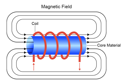
Figure 1: Electrical Model of an Inductor
Inductors are formed using insulated wire wound as a coil. The coil can be different shapes and sizes, and can be wound using different core materials.
The inductance is dependent on multiple factors, such as the number of turns, core dimensions, and permeability. Figure 2 shows key inductor parameters.
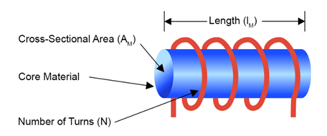
Figure 2: Inductor Parameters
Table 1 shows how to calculate inductance (L).
Table 1: Calculating Inductance (L)
| Equation | Parameter | Parameter Description |
| $$L = \frac {µ_r µ_0 \times A_M}{I_M} \times N^2$$ | µ = µr µ0 | Permeability |
| µr | Relative permeability (core) | |
| µ0 = 4π10-7 | Constant of nature | |
| AM | Area of the coil (magnetic field area) | |
| IM | Coil length (magnetic field length) | |
| N | Number of turns |
Common inductor parameters are described in more detail below.
Permeability
Magnetic permeability is the ability for a material to respond to magnetic flux, as well as how much magnetic flux that can pass through the inductor within an applied electromagnetic field. Table 2 shows how to the permeability can intensify the magnetic flux density (B).
Table 2: Calculating the Magnetic Flux Density (B)
| Equation | Parameter | Parameter Description |
| $$B = µ \times H$$ | $$µ$$ | The medium's permeability |
| $$H$$ | The magnetic field (dependent on the geometry, number of turns, and current) |
Based on Table 2, the magnetic flux concentration depends on the core permeability and dimensions.
Figure 3 shows a coil without a core.
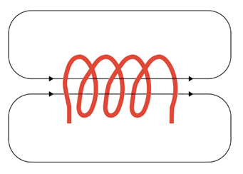
Figure 3: Air Coil
The air coil’s permeability is a constant value (µr air) that is about equal to 1.
Figure 4 shows an inductor with a core. Note that when a core is used, the magnetic field is intensified.
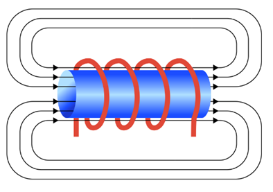
Figure 4: Inductor with a Core
For the magnetic core, the typical permeability varies for different core materials. Table 3 lists the permeability of three different core materials.
Table 3: Magnetic Core Permeability
| Core Material | Notation | Permeability |
| Iron | µr FEBASED | 50 to 150 |
| Nickel-zinc | µr NiZn | 40 to 1,500 |
| Manganese-zinc | µr MnZn | 300 to 20,000 |
Related Content
-
ARTICLE

Surface-Mounted Inductors Optimized for MPS ICs
Find the ideal power inductor for your application
-
CATEGORY PAGE
Inductors
Explore MPS's inductor products
-
ARTICLE
How to Avoid Inductor Saturation in your Power Supply Design
Discover how magnetics can saturate and how to avoid it in your design
-
ARTICLE
A Perfect Match: Power Losses in Buck Converters and How to Increase Efficiency
Get the most out of your buck converters
Inductance (L)
Inductance is the ability for an inductor to store induced electric energy as magnetic energy. An inductor must supply constant DC current to the output load while being driven by the switching input voltage.
Table 4 shows the relationship between the current and the inductor’s voltage. Note that the voltage across the inductor is proportional to the change of current with respect the time.
Table 4: Calculating the Inductor's Voltage Drop
| Equation | Parameter | Parameter Description |
| $$v = L \times \frac {di}{dt}$$ | $$v$$ | Voltage drop across the inductor |
| $$\frac {di}{dt}$$ | Rate of change for the current |
First, determine the inductance range for your design, keeping in mind that inductance is not constant across operating conditions. Inductance can change as frequency increases, which requires special consideration for applications with higher switching frequencies. Inductor manufacturers typically test inductance at frequencies between 100kHz and 500kHz, since most DC/DC converters operate within this range.
Resistance (R)
The inductor’s current resistance results in heat dissipation, which affects efficiency. The total copper losses are comprised of the RDC and RAC losses. RDC is constant regardless of the frequency, while RAC is dependent from the frequency. Table 5 shows how to calculate RDC.
Table 5: Calculating Cooper RDC
| Equation | Parameter | Parameter Description |
| $$R_{DC} = ρ \times \frac {I}{A}$$ | $$ρ$$ | Resistivity |
| $$I$$ | Length | |
| $$A$$ | Cross-sectional area |
The only way to reduce copper losses is to increase the area of the wire, either by switching to a thicker wire or using a flat wire. When using a flat wire, the winding window is completely used, which results in a lower RDC. Table 6 shows the cross-section area for a round wire versus flat wire.
Table 6: Comparison Cross-Sectional Area Round vs. Flat Wire
| Dimensions | Type of Wire | Comparison | Cross-Sectional Area | |
| 1mm Diameter | Round |  |
 |
$$A_{ROUND} = πr^2 = π \times 0.5^2 = 0.785mm^2$$ |
| 1mm x 1mm (base/height) | Flat |  |
$$A_{FLAT} = 1 \times 1 = 1mm^2$$ | |
Table 7 compares the advantages of round and flat wires.
Table 7: Round vs. Flat Wires
| Round Wire | Flat Wire |
|
|
Estimate the inductor’s DC copper loss (PDC) with Equation (1):
$$P_{DC} = I^2_{DC} \times R_{DC}$$The copper loss (PAC) is based on RAC, which is caused by the proximity and skin effect, which is driven by the frequency. The higher the frequency, the higher the PAC copper losses.
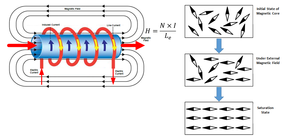
Core Losses
Generally, the magnetic properties required for core-based inductors can be met with ferromagnetic material. Depending on the core’s material, the relative permeability of this inductor ranges between 50 and 20000.
The domain structure of this material responds when a magnetic field is applied; without a magnetic field, the orientation is random. Core losses are generated when the magnetic energy changes. The domains orient the magnetic moment along the magnetic field direction. As the domains expand and contract, some of the domains get stuck in the crystal structure. Once the stuck domains are able to rotate, the energy dissipates as heat.
Ripple Current (∆IL)
The ripple current (∆IL) is the amount by which the current changes during a switching cycle.
The inductor may not perform properly when it operates outside of its peak current range. An inductor’s ripple current is typically designed to be within 30% to 40% of the IRMS.
Figure 5 shows the inductor current waveform.
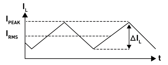
Figure 5: Inductor Current Waveform
Rated Current (IDC, IRMS)
The rated current refers to the DC current required to increase the inductor’s temperature by a specified amount. The temperature rise (ΔT) is not a standard value, though it is usually between 20K and 40K.
The rated current is measured at the ambient temperature. This current is provided in the inductor datasheet, and is the value expected for a final application. For applications with higher ambient temperatures, designers should select an inductor with a higher self-heating temperature.
Figure 6 shows the temperature rise in relation to the rated current. This curve can be used to determine the current for any temperature rise.
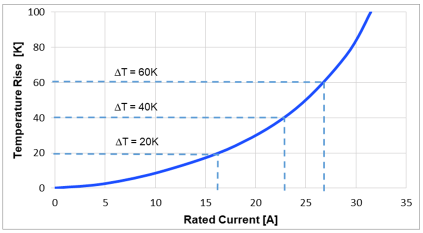
Figure 6: Inductor Rated Current Curve
The operating temperature (TOP) in an application is determined by the ambient temperature (TAMB) and the inductor’s self-heating value (ΔT). TOP can be estimated with Equation (2):
$$T_{OP} = T_{AMB} + ΔT$$The given rated current is a good way to estimate an inductor’s temperature rise. Temperature increase is also influenced by the circuit design, PCB layout, proximity to other components, and trace dimensions and thickness. Additional heat may also be caused by an excess of AC loss generated in the inductor core body and windings.
Use an inductor with a larger package size if lower self-heating is required.
Saturation Current (ISAT)
The saturation current ratings refer to the DC current that the inductor can support before the nominal inductance drops by a defined percentage.
The reference percent drop is unique to each inductor. Generally, manufacturers set this value between 20% and 35%, which can make comparing inductors difficult. In datasheets, it is common to find a curve showing how the inductance changes in relation to the DC current. This curve can be used to evaluate the entire inductance range and how it corresponds to the DC current.
The DC saturation current depends on the temperature and the inductor’s magnetic material and the structure of its core. Different structures and magnetic cores can affect ISAT.
Ferrite drum cores are the most common, and they are characterized by a hard saturation curve (see Figure 7). Is it critical to ensure that the inductor does not operate beyond the drop point, as the inductance drops significantly and functionality is reduced beyond this point.
Composite molded inductors have stable inductance drops across temperature changes, with soft saturation. Soft saturation provides the designers more flexibility and wider operating ranges due the gradual inductance drop.
Figure 7 shows two saturation curves. The blue curve shows an example of soft saturation with a typical composite molded inductor. The red curve shows an example of hard saturation with a typical NiZn/MnZn drum core.
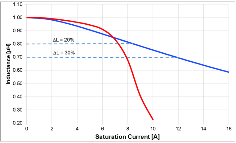
Figure 7: Inductor Saturation Current Curve
A smaller inductance (or a larger package size) allows inductors to handle higher saturation currents.
Self-Resonant Frequency and Impedance
The self-resonant frequency (fR) of an inductor is the lowest frequency at which the inductor resonates with its self-capacitance. At the resonant frequency, the impedance is at its maximum peak, and the effective inductance is zero. Figure 8 shows the inductor’s circuit model.
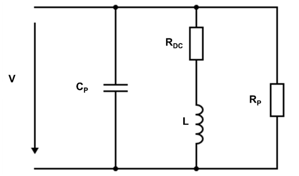
Figure 8: Inductor Circuit Model
An inductor has inductive characteristics (shown as the blue curve Figure 9) up to the resonant frequency (fR), as an increasing frequency corresponds to a higher impedance. At the resonant frequency, the negative capacitive reactance (XC) is equal to the positive inductive reactance (XL), estimated by the condition in Equation (3):
$$X_L = X_C \to jωL = \frac {1}{jωC}$$Beyond the resonant frequency (shown as the red curve Figure 9), the inductor displays capacitive characteristics that correspond to a decreasing impedance. After this point, the inductor does not function as expected.
Figure 9 shows the relationship between inductance and frequency.
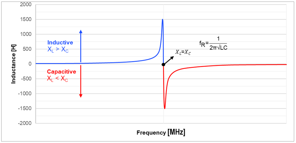
Figure 9: Inductance vs. Frequency
Selecting a Cost-Effective and Compact Inductors
It is simple for a designer to choose a sufficient inductor once they understand the basic meaning behind each parameter in an inductor’s datasheet. However, if a designer knows the details behind each parameter, they can choose the optimal inductor for a DC/DC converter application, and predict how the system will perform under different conditions.
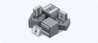
Monolithic Power Systems supplies a wide array of power inductors for applications ranging from power supplies to power converters. In particular, the MPL-SE inductor series are semi-shielded inductors covered by an external magnetic epoxy resin to improve magnetic characteristics.
The molded inductor series offers soft saturation, providing stable behavior at high operating temperatures. These molded inductors feature low DC and AC resistances and can handle high currents. In addition, the molded construction reduces audible noise generated from alternating currents and pulse wave frequencies. Choose the optimal inductor based on the following criteria:
- Choose the low-profile MPL-AT molded series when height is a design restriction.
- Choose the MPL-AY molded series when an application requires a high current capability
- Choose the MPL-AL molded series for high-efficiency applications.
Monolithic Power Systems inductors and DC/DC power converters provide an easy, complete power solution for your design.
Conclusion
There are a wide variety of inductors on the market for different applications, and it can be difficult to select the optimal inductor. For example, larger-value inductors reduce DC losses an improve efficiency, but they are physically larger and they retain more heat.
Because there is no one-size-fits-all inductor, it is vital to understand each inductor’s parameters, as well as the relationships between different parameters. This can help designers determine how an inductor would perform in a particular DC/DC application, and aid in inductor selection when looking at MPS’s semi-shielded inductors and molded inductors.
_______________________
Did you find this interesting? Get valuable resources straight to your inbox - sent out once per month!
Technical Forum
 Latest activity 2 months ago
 5 Comments
Latest activity 3 years ago
4 Comments
Latest activity 4 years ago
2 Comments
5 Comments
Latest activity 3 years ago
4 Comments
Latest activity 4 years ago
2 Comments
Log in to your account
Create New Account