Introduction: Force Measurement With Arduino and Data Logger (GUI)


Earlier this year, we published an instructable showing how we build our own mini-extruder. It was part of a one year engineering school project which aimed to develop a new sustainable material for large scale 3D printing. During our researches on this new material, we developped a device to measure the force needed to extrude it with our mini-extruder.
This instructable aims to explain how we conceived this device. You will discover how it was designed and what were the encountered difficulties. You will also learn about the basics of using a load cell (which can be usefull for many projects). Finally you will also see how we coded our own Graphical User Interface (GUI) to acquire the data we wished to measure.
Supplies


Here is the list of the needed materials and some links to purchase it :
- Basic PLA for 3D printing the mechanical parts (3D printer was a Creality ender 3)
- "Button" load cell 200kg for uniaxial force measurement
- SparFun load cell amplifier - HX711 essential for force measurement
- An arduino board, we used an Arduino UNO because we had it at the school
- Some wires
- a 4 mm threaded rod (7 cm of length)
Step 1: The Design of the Device


If you have not read our first instructable on our prototype of mini-extruder, we will just recall the basics of how it works so that you can understand how we designed our device.
Basically we want to extrude a paste material through a custom made syringe. The material is pushed through the syringe thanks to a piston matching the diameter of the syringe. You can see the extruder on the attached picture. One easily understands all the force needed to extrude the material goes through the piston. This is why we decided to create a custom piston which will contain a load cell to measure the extrusion force.
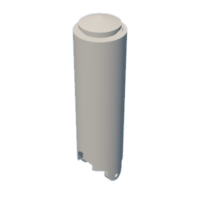
Once our idea was settled, we used CATIA V5 (but you can use whatever software you want) to create the 3D models of our custom piston. The piston is composed of 2 different parts and the button load cell is inserted between them. You can see the 3D models of these parts on the attached pictures. The 2 parts of the piston are attached together thanks to a 4mm threaded rod which fits in the dedicated holes. We added a little bit of play when we designed the holes so that the 2 parts are allowed to move a litlle bit when a force is applyed. This helps for the force measurement and makes it easier for the piston to enter the syringe.
We made a 3D model of the load cell and created an assembly in CATIA to check if everything fitted together.
Step 2: Modification of the Design After Some Tests


As one can observe by looking at the photo of the load cell, there is a small button on top of it. It is on this part of the load cell that you have lean to measure a force. In our case, it is the upper part of the piston which will lean on it. The issue is that this piston will be printed in PLA and the section of the button is really small. Hence the constraint created by the button of the load cell on the upper part of the piston is really high. In fact it is so high that during our first test of the device, we observed that it had permanently deformed our PLA printed part... We had reached the elastic limit of our PLA. On the attached picture, you can see on the top the underformed part and below it is the damaged part.
To overcome this issue, we machined a small steel part to insert between the button of the load cell and the upper part of the piston. This steel part is sufficiently resistant so that it wont be deformed by the button of the cell. You can see a cut of the last version of the 3D.
You can find attached to this section the last version of the 3D models in stl format

Step 3: The Basics of Using a Load Cell


In this project, we seek to measure a force. But do you know what "measuring a force" really means ? In fact you can't measure it directly. One thing you can do instead is to measure a tension by using what is called a strain jauge load cell. It is a device which usually contains 4 strain jauges in a wheatstone bridge configuration. Basically a strain jauge is small strip which resistivity varies with its dimension. This means that when the strip is deformed its resistivity will change. Hence if you apply a current you can measure this difference of resistance (in fact you measure a difference of tension) and with a propper calibration of your device, you can have a measure of the deformation of your load cell and, assuming the deformation is in the elastic domain you just got yourself a measure of the force which is applyed. I won't go into much more details but hopefully you now have an idea of a how a load cell works. If you want to learn more about wheatstone bridge and load cell there are plenty of documentation on the web. Sparkfun has a really good and understandable document on the subject.
Once we knew we were going to use a strain jauge load cell, we had to chose which type of strain jauge load cell we were going to use. As we want to measure an uniaxial force, we chose a "button" type load cell which is adapted to this kind of measurement.
Now that we have chose our load cell we should be able to measure some force by pairing it with Arduino right ?? Well... It is not that easy. As we said, we are going to measure a variation of tension which is proportional to the derformation of the strain jauges of the load cell. The issue is that most of the time the deformations of the strain jauges are reaaaaally low. Hence the tension variation is also really low. This document made by SparkFun gives order of magnitude and more explanations. Basically for a strange jauge having a resistance of 120 ohms, you can expect a variation of tension of about 0.12 ohms... Most of the devices you could use to measure a variation of tension would not detect it.
One solution is to use an amplifier. We chose the HX711 from SparkFun because it is cheap, seemed reliable and is compatible with an Arduino board. We simply had to download the dedicated Arduino library as explained in this tutorial. Now we are ready to build the circuit according to the attached image and we should be able to do some measurements by using the provided code !
Step 4: How to Save the Data You Have Measured
Now that we were able to do some measurements, we had one last challenge to overcome : How could we store the data we just measured ?
In fact, we were able to read our measurements in the serial monitor of the Arduino IDE but we could not store them. We could have ctrl + C/ ctrl + V the serial monitor but it was not a satisfying solution from our point of view. We thought of 2 other solutions :
- Recording the data on an SD card by using dedicated Arduino Libraries
- Recording the data on the computer linked with Arduino by using an external piece of code written in python for instance
We chose the last solution because we had notions in python and moreover it allowed us to have a graphical interface for the recording of the data. We used the python package pyserial which allows a user to send and read informations via the USB port of a computer. Here is an excellent tutorial to learn the basics of the package and how to use it with Arduino (sorry it is in French but I guess some good tutorials also exist in english). Basically, this package will allow your computer and the Arduino to understand each other and to communicate.
In the .ino file you will be able to read what you sent by USB port with a dedicated function we wrote :
String readSerialMonitor(int t_letter) {
String command;
while (Serial.available() > 0)//Check if there is some data in the monitor
{
     t_letter = Serial.read();
     command += char(t_letter);
     delay(1);
}
return command;
}
And you will be able to send to your computer (via the USB port) the data read by the Arduino (Serial.print()) and deal with them in the python code. We could have done a mere python code to store the measured data in a .txt file but we decided to code a GUI to make our device more convinient to use
Attachments

Step 5: Creating a GUI for Our Data Logger


We decided to create a Graphical User Interface (GUI) for our data logger. As we already used python to store ou data it seemed logic to use python to create the GUI. We found a python package called tkinter which seemed to be perfectly adapted to what we wanted to do. With some more researches we found a great work which was done by a guy named DRSEE who did exactly what we seeked to do. Here is the link of his video and the link of his github repo. All the credits go to him, we simply understood what he wrote in his code rx_threading.py and used it to create our own GUI. It is inspired by the one DRSEE presents in his video. We also added elements to start and stops the data acquisition. The main thing you have to pay attention to is to match your python script with your Arduino program so that they understant each other.
You can find attach a schematic of how our entire data logger works.
To use the GUI, you simply have to launch the python script, plug the Arduino to the computer on which the python script is running and launch on the Arduino the .ino code. Then you choose the corresponding COM port (the one you plugged the Arduino in). Don't forget to match the baudrate of the GUI with the one of the Arduino (otherwise your computer and the Arduino won't be able to understand each other). And here you go, you simply have to press "start acquisition" !
Step 6: Load Cell Calibration


At this point everything was ready. We simply had to do the calibration of our load cell so that the data we record corresponds to the real force which is applyed. To do this we could have used the dedicated settings, scripts and tutorial provided by sparkfun, but we decided to do it differently. At our school we could have access to a mechanical press with a calibrated load cell. We decided to use it to do the calibration of our load cell. You can see a photo of the testing set up attached in this step. We applyed various level of forces on our load cell, average the results of each applied level of force and plot it with the measurements of the mechanical press. We obtain a linear trend and were able to correct the measure in our script. We repeated the process until eventually we get an equation which was really close to "our measure = press measure". That is y = x.
Step 7: Measuring the Friction Forces in the Syringe
In our case, the piston containing the load cell goes through a syringe. The end of our piston is made of a rubber part for watertightness. But this means the rubber part rubs on the syringe wall and the corresponding friction force is included in the force we measure whereas we only want to measure the force needed to extrude our material. In order to have a propper force measurement, we measured the friction force multiple times by moving the piston in an empty syringe. We did that for various extrusion speed and manage to get a friction force value for each extrusion speed which we substracted to force we measured with our load cell.
Step 8: Finally Doing Some Measures !


Once everything was put together, the calibration was done and we took care of the friction forces, we could finally do some measurement by combining our force measurement device with our mini extruder ! You can see attached a photo of prototype while our team is using it and a screenshot of a graph illustrating the measurement we made !
We hope you have learned something while reading about our project ;)


