


® Volume 24 Number 4 - April 2024



03. Guest comment
Thure Cannon, President, Texas Pipeline Association.
05. Pipeline news
Contract news and an update on the Iran-Pakistan gas pipeline project.
KEYNOTE: COMPLIANCE AND STANDARDS
09. Unveiling the blind spot
Paul Stockwell, Managing Director, Process Vision, describes how current standards fail to detect liquid carryover in gas processing.
15. The power of proactivity
Phanindra Kanakamedala and Greg Morrow, Emerson, USA.
DAMAGE AND DEFECT ASSESSMENT
21. Evaluation of growing corrosion
Fadillah Syahputra, Zugao Chen and Tim Zhang, Deyuan Pipeline Technology Co., Ltd, China.
25. Detecting a pipeline pulse Simon Bell, iNPIPE PRODUCTS, UK.
INTEGRITY AND INSPECTION
29. New approach to pipeline detection
Luigi Kassir and Josh Pendleton, Skipper NDT.
COATINGS AND CORROSION
33. Setting new standards for epoxy coatings
Glen Grundberg, General Manager of Denso North America Inc., Canada (a member of Winn & Coales International Ltd).
HOT TAPPING AND LINE STOPPING
39. Not just another weld
Frede Maxwell, Brian Anderson, Paul Gonzales, Darren Sutherland, Bie Cornell and Dave Albertson, WeldFit.
CATHODIC PROTECTION
45. Decouplers making a difference
Jay Warner, Dairyland Electrical Industries, USA.
50. The ranges of CP monitoring
David Celine, Managing Director, Omniflex.


HDD
55. Ramming home trenchless technology
Anne Knour, Tracto Technik, Germany.
PIPELAYING AND VESSELS
61. CO2 systems, studies and solutions
Alessandro Terenzi, Giorgio Arcangeletti, Enrico Bonato, Elvira Aloigi, Lorenzo Maggiore, and Annalisa Di Felice, Saipem S.p.A.
OFFSHORE AND SUBSEA
68. Deriving value from offshore data
Neil Skene, Imrandd Ltd, UK.


ISSN 14727390 Member of ABC Audit Bureau of Circulations ON THIS MONTH'S COVER Reader enquiries [www.worldpipelines.com] C O NTENTS Copyright© Palladian Publications Ltd 2024. All rights reserved. No part of this publication may be reproduced, stored in a retrieval system, or transmitted in any form or by any means, electronic, mechanical, photocopying, recording or otherwise, without the prior permission of the copyright owner. All views expressed in this journal are those of the respective contributors and are not necessarily the opinions of the publisher, neither do the publishers endorse any of the claims made in the articles or the advertisements. Printed in the UK. WORLD PIPELINES | VOLUME 24 | NUMBER 04 | APRIL 2024 Founded in 1990, 3X ENGINEERING (3X) is a global leader in critical industrial assets repair using composite technology. Developer, manufacturer, seller and installer of our products we offer to our clients a complete integrated service. From our head offices in Monaco, we operate worldwide, in any environments (Onshore, Offshore and Subsea), thanks to our large qualified distribution network of over 60 partners. For more information, visit www.3xeng.com.
45 CBP019982 25 ® Volume 24 Number 4 - April 2024
PAGE 68 61
PAGE 50
ranges of CP monitoring Industrial pipelines, which are under constant threat from corrosion, are critical pieces of infrastructure that must be occur. However, engineers and asset managers regularly face challenges in monitoring CP systems in pipeline applications Here David Celine, Managing Director of remote monitoring specialist Omniflex, explains why, in plant environment, engineers and plant managers should opt for short range system performance and pipeline corrosion levels. CP systems come in two main forms: galvanic CP and where buried or submerged steel structure connected to metal alloy with more negative electrode potential than it, cell, and the metal alloy becomes sacrificial anode that is consumed by corrosion, rather than damaging the structure. have fully corroded, ensuring ongoing protection. In ICCP systems, current externally injected into the structure to ensure that the structure remains cathodic with anodes that are connected to DC power source by way of transformer/rectifier (T/R), which is normally powered by the David Celine, Managing Director, Omniflex, explains why engineers should opt for short range wireless technology to monitor ongoing CP system performance and pipeline corrosion levels. 50 51
The

GUEST COMMENT

Natural gas – transported safely and efficiently by pipelines – delivers the products we need and use every single day. Recent political developments in the US, however, may threaten the country’s – and our allies’ – energy security, as well as the development of the cleanest and most reliable natural gas industry in the world.
The Texas Pipeline Association (TPA) is the largest state trade association in the US representing solely the interests of the intrastate pipeline network. Its midstream member companies deliver the large quantities of natural gas, crude and the refined petroleum products that are in just about every item on the market today, including plastics, medicines and clothing. These are products the state, the nation and the world cannot do without.
In addition, the Texas oil and natural gas industry is an economic powerhouse. In 2023, it paid state and local taxes and state royalties totalling US$26.3 billion, equating to more than US$72 million each day.1 And in FY 2023, the industry employed 480 176 Texans. Since 2007, the Texas oil and natural gas industry has paid more than US$230.3 billion in state and local taxes and state royalties. No other single industry in Texas can claim anything close to such impressive statistics.
However, the Biden Administration recently froze LNG export permitting
to non-free trade agreement countries, threatening our energy, economic and national security, while providing no major environmental benefits. Along with 31 other state and national oil and natural gas and business organisations, TPA wrote to Biden’s Department of Energy Secretary Jennifer Granholm this past January to argue that restricting LNG exports “puts American jobs and allies at risk, while undermining global climate controls.”
The letter warned that the pause would undercut Biden’s own commitment to supplying American allies with reliable energy. “While our European allies have made significant strides in reducing their reliance on Russian natural gas thanks to American energy producers, Europe faces a considerable supply gap over the longterm that should be met by American energy, not hostile nations,” the letter said. In late March, 16 states, including Texas, sued the federal government over its ban on LNG permits.
The LNG pause is just one more example of the current federal interference that threatens Texas’s vaunted innovation, development and growth of a natural gas and infrastructure system that is the envy of the world. To understand why the state’s market-driven approach is so successful, it is vital to understand the difference between interstate and intrastate pipelines.
There are approximately 489 657 pipeline miles in the state, of which 439 922 are intrastate.2
The intrastate industry is regulated primarily by the Railroad Commission of Texas (RRC) and is based on a freemarket system that is designed to ensure a safe, affordable and abundant supply of energy. Prices are set by market forces. Neither the RRC, the state of Texas nor any state or federal agency has the power to set the price of natural gas.
The Texas intrastate market is an independent competitive market that
allows pipelines to be built when there is sufficient market demand. Pipelines can begin construction once the permit is approved (often in less than a year) and ultimately are built in a timely manner to meet ever-increasing demand. Transportation rates are negotiated between shippers and pipeline companies.
Conversely, at the federal level, the Federal Energy Regulatory Commission (FERC) regulates interstate pipes and determines if new interstate pipelines are necessary, whether they can be constructed, their location and the maximum rate of transportation based on cost-of-service. New pipelines can only be built after these determinations have been made, often taking years and thus restricting access to abundant natural gas.
This excessive federal involvement causes major slowdowns during the building of new infrastructure at a time when demand for power in the US is at its highest and continues to grow.
Instead, our market-based system has delivered tremendous success in a state where Texas legislators have worked diligently to keep energy prices low and supplies abundant – just one of the reasons why the population and economy is booming.3 The state is now the nation’s second most populous – and the number of energy-hungry businesses that have moved to the state continues to grow. Consumers win as well, with the state boasting some of the lowest energy costs in the nation.
Left unfettered by unnecessary regulation, Texas wins, along with our European allies and global emission goals, as we continue to produce and deliver some of the safest, most reliable and efficient natural gas and hydrocarbons in the world. 1.
2023 Annual Energy & Economic Impact Report, TXOGA, January 30, 2023.
Texas Pipeline System Mileage, Railroad Commission of Texas; 2024.
US Census Bureau, Texas population.
2.
3.
THURE CANNON President of the Texas Pipeline Association (TPA)

The experts you can trust CRC Evans’ market-leading welding and coating services, technologies and equipment ensures efficient, on-time delivery of your global onshore and offshore energy projects. Americas Europe Middle East Africa Asia Pacific crcevans.com enquiries@crce.com @crcevansglobal
WORLD NEWS
EQT agrees to buy Equitrans Midstream
US natural gas producer EQT Corp has agreed to buy Equitrans Midstream in an all-stock deal that values its former pipeline unit at about US$14 billion including debt, as companies look to navigate decade-low prices for the commodity, reports Reuters.
Merger activity in US shale oil and gas has soared in pursuit of greater scale and cost efficiencies amid volatile prices, with US$250 billion in deals in the oil and gas industry in 2023.
The combination will allow EQT to lower costs to produce and transport its natural gas to market by adding more than 2000 miles of pipelines, the companies said on Monday.
“The only way to truly thrive in this world is to be at the low end of the cost curve,” EQT Finance Chief Jeremy Knop said on a conference call with analysts.
But investors were unimpressed by the combined company’s US$13.4 billion in debt and US$250 million a year in
potential synergies. EQT shares fell 8% to US$34.53 while Equitran rose 2.7% to US$11.55 in midday trading. At the current price of EQT, the offer would be valued at US$12.10 per share.
“While operationally we like the combination, the deal adds an equity overhang as midstream holders may have different priorities, and the incremental debt likely directs EQT’s free cash flow to leverage reduction over all other options for the near-term, which we expect to result in the shares trading down,” said Bertrand Donnes, analyst at Truist Securities.
A global gas glut has pummelled prices, forcing producers to curb output and spending on drilling activity. EQT, which has been an aggressive consolidator, is curtailing nearly 1 billion ft³/d of natural gas production this month.
The deal is expected to help lift margins by gaining better control of pipeline costs and processing as EQT pushes to get global prices via greater exposure to LNG export markets.
PHMSA opens US$18 million funding opportunities for pipeline and safety activities
The US Department of Transportation’s Pipeline and Hazardous Materials Safety Administration (PHMSA) has published multiple Notices of Funding Opportunities (NOFOs) to award US$18 million in grants through its pipeline and hazardous materials safety programmes.
These funding opportunities are open to states, local communities, tribal entities, universities, and non-profit organisations to support pipeline and hazardous materials safety programmes across the USA.
First phase of Iran-Pakistan gas pipeline approved
The Pakistan Ministry of Energy has announced the approval of the first phase of the Iran-Pakistan (IP) gas pipeline by the Cabinet Committee on Energy (CCoE).
The decision, which comes after approximately 10 years of postponement, is set to enhance the nation’s energy security.
During its recent session, the CCoE considered a summary from the Petroleum Division regarding the IP Gas Pipeline. The committee endorsed the recommendations of the Ministerial Oversight Committee for the project, which was established by caretaker Prime Minister Anwaar-ul-Haq Kakar in September 2023.
Funding will be used to improve community and environmental safety through projects that train first responders, educate the public on local safety initiatives, encourage the development of new pipeline technologies, and more.
“Local authorities and emergency responders are often the first on the scene after a pipeline or hazmat transportation incident, and the Biden-Harris administration is proud to support them with additional training and resources,” said US Transportation Secretary Pete Buttigieg.
The approved work includes the construction of an 80 km section of the pipeline within Pakistan, extending from the border to Gwadar. The pipeline will bring natural gas from Iran’s South Paras Gas field.
Inter State Gas Systems will execute the project, with funding sourced from Gas Infrastructure Development. Iran has set a 180 day deadline for Pakistan, expiring in September 2024, to begin the pipeline’s construction, according to reports.
The 781 km pipeline, which is due to run from the Iranian border to Pakistan’s port city of Gwadar, will have estimated capacity of 750 million ft3/d to around 1 billion ft3/d.
GlobalData: pipelines set to dominate US oil and gas midstream projects
The trunk/transmission pipelines segment is set to dominate upcoming oil and gas midstream projects in the US by 2028, accounting for about 47% of the midstream projects starting between 2024 and 2028, says GlobalData, a leading data and analytics company.
GlobalData’s latest report, ‘North America Oil and Gas Projects by Development Stage, Capacity, Capex, Contractor Details of All New Build and Expansion Projects to 2028,’ reveals that 186 midstream projects are expected to start operations in the US during the period 2024 – 28. Out of these, the trunk/ transmission pipelines segment alone constitutes 87 projects, followed by gas processing and LNG with 34 and 29, respectively.
Bhargavi Gandham, Oil & Gas Analyst at GlobalData, comments: “The midstream sector in the US continues to grow
due to rising production from shale plays, necessitating infrastructure expansion for transportation and storage. Rising exports of oil and gas are providing additional momentum to the sector’s growth.”
Among the upcoming transmission pipeline projects in the US by 2028, WEST Header Project is a key project with a pipeline length of 1046 km. To be operated by Magnum Development LLC, the natural gas pipeline project is expected to commence operations in 2028.
Gandham concludes: “The US boasts one of the world’s most extensive oil and gas transmission pipeline networks, with plans for new pipelines, particularly in natural gas, aimed at lowering domestic carbon emissions and facilitating LNG exports.”
APRIL 2024 / World Pipelines 5
EVENTS DIARY
8 - 11 April 2024
CONTRACT NEWS
DeepOcean to inspect pipelines for Equinor
Pipeline Technology Conference (ptc) 2024
Berlin, Germany
www.pipeline-conference.com
15 - 19 April 2024
TUBE Düsseldorf 2024
Düsseldorf, Germany
www.tube-tradefair.com
6 - 9 May 2024
Offshore Technology Conference (OTC) 2024
Houston, USA
www.2024.otcnet.org
11 - 13 June 2024
Global Energy Show 2024
Calgary, Canada
www.globalenergyshow.com
26 - 27 June 2024
Hydrogen Technology Conference & Expo 2024
Houston, USA
www.hydrogen-expo.com
26 - 29 August 2024
ONS 2024
Stavanger, Norway
www.ons.no
9 - 13 September 2024
IPLOCA convention
Sorrento, Italy
www.iploca.com/events/annual-convention
17 - 20 September 2024
Gastech 2024
Houston, USA
www.gastechevent.com
24 - 26 September 2024
International Pipeline Conference & Expo (IPE) 2024
Calgary, Canada
www.internationalpipelineexposition.com
Ocean services provider DeepOcean has been awarded a contract by Equinor to deliver pipeline inspection and survey scopes on the operator’s pipelines in the North Sea.
In addition to its extensive infield pipeline networks, Equinor also has operational responsibility for the world’s most extensive subsea pipeline system for transportation of gas.
DeepOcean’s scope of work includes pipeline inspections, seabed mapping, and ad-hoc pipeline survey and light construction work. The agreement is valid for 2024.
The latest contract is an additional award under DeepOcean’s frame agreement with Equinor for the provision of offshore survey services. DeepOcean has not
Corinth Pipeworks to be CO2 pipe contractor
Corinth Pipeworks has been selected as a contractor by Northern Endurance Partnership (UK), for an offshore pipeline to transport and store millions of t of carbon dioxide (CO2) emissions safely in the UK North Sea to an offshore geological storage site named the Endurance Store.
Northern Endurance Partnership (NEP), a joint venture between bp, Equinor, and TotalEnergies, is the CO2 transportation and storage provider for the East Coast Cluster (ECC).
The infrastructure will serve the Teessidebased carbon capture projects – NZT Power, H2Teesside and Teesside Hydrogen CO2 Capture. NEP aims to support the UK’s net-zero commitments by developing the world’s first zero-carbon industrial hub by 2030.
LIBERTY Steel selected for UK carbon capture pipeline contract
LIBERTY Steel has announced that its Hartlepool pipes division has been selected for a major contract to supply pipelines to the key UK energy infrastructure development by Northern Endurance Partnership (NEP) and Net Zero Teesside Power (NZT Power) making significant cuts to UK carbon emissions.
LIBERTY Pipes Hartlepool (LPH) will deliver onshore and offshore linepipe to the Teessidebased project, one of eight EPC packages awarded with a combined value of around £4 billion.
disclosed the value of the new contract.
“We are proud to continue to support Equinor with subsea services in the North Sea. We will utilise the vessel Edda Flora with our Superior Survey ROV to perform the survey work,” says Trond Hagland, Commercial Manager – Survey and Inspection at DeepOcean.
The Superior Survey ROV provides unmatched ROV survey performance. Its hydrodynamic shape, power and modular design provides excellent operational versatility and data quality. The ROV is equipped with the latest navigation and sensor system technologies.
DeepOcean will manage the contract delivery out of its headquarters in Haugesund, Norway, supported by the company’s operation in Aberdeen, UK.

6 World Pipelines / APRIL 2024 Follow us on LinkedIn to read more about the articles linkedin.com/showcase/worldpipelines ON OUR WEBSITE • CEZ to acquire majority stake in GasNet • Decom strengthens position in AsiaPac with three contract successes • Vopak signs agreement with Air Liquide • ABL secures subsea contract for US Gulf of Mexico project • Corcovado Geosub signs contract with Kongsberg Discovery • OPITO launches new global standard for offshore safety
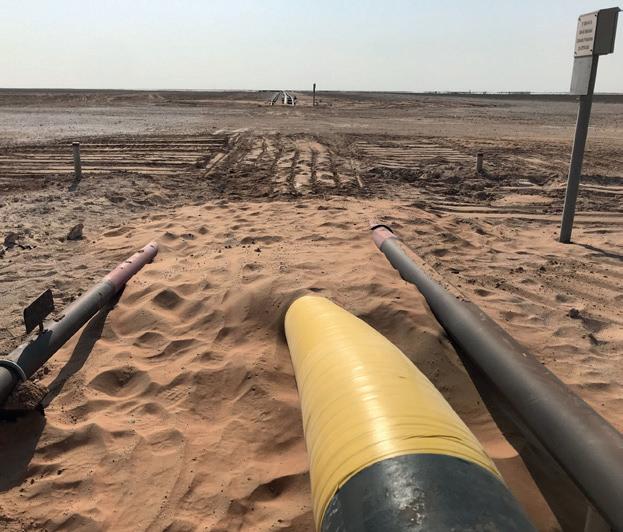

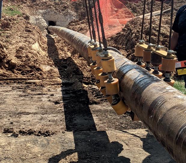


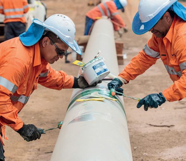

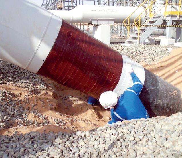

HEAT SHRINKABLE SLEEVES
DENSO™ are leaders in corrosion prevention and sealing technology. With 140 years’ service to industry, our mainline and field joint coating solutions offer reliable and cost effective protection for buried pipelines worldwide.
FOR CORROSION
United Kingdom, UAE & India USA & Canada
Australia & New Zealand Republic of South Africa


www.denso.net
www.densona.com
www.densoaustralia.com.au
www.denso.co.za
PROTECTIVE OUTERWRAPS
LIQUID EPOXY COATINGS
PETROLATUM TAPE WRAP SYSTEMS
SOIL-TO-AIR INTERFACE
BUTYL TAPE WRAP SYSTEMS
INTERNAL PIPE LININGS
BITUMEN TAPE WRAP SYSTEMS
A MEMBER OF WINN & COALES INTERNATIONAL
PREVENTION
VISCO-ELASTIC COATINGS
CUSTOMIZED CALIPER TECHNOLOGIES WITH IMU MAPPING
Rugged
WWW.GEOCORR.COM
Equipment For New Construction & Highly Sensitive Tools For In-Service Pipelines

Liquid carryover in gas processing is a significant problem, leading to limitations on gas flow, production losses and increased operational costs due to foaming, fouling, and chemical usage. Liquid carryover in the export gas from gas processing plants, can also lead to higher maintenance costs and serious safety issues at compressor stations, LNG plants and gas turbine power stations. Traditional monitoring systems often fail to detect this problem, giving a false impression of ‘dry gas’. Permanent monitoring systems for phase separation and filtration are currently inadequate. The industry is now adopting real-time monitoring through process cameras to identify issues like mist or stratified flows, thereby
Paul Stockwell, Managing Director, Process Vision, describes how current standards fail to detect liquid carryover in gas processing.
9

improving the balance between processing trains and reducing costs. Traditional gas sampling systems that adhere to API and ISO standards may miss liquid carryover events, leading to financial losses. New process camera systems can capture these events, improving the validation and uncertainty of fiscal metrics like flow and calorific value.
Liquid carryover in gas processing
A detailed survey by Amine Experts studied 400 cases of amine plant failures, finding that these failures cost operators between US$250 000 and US$250 million each.1 The survey identified three main causes of failure: poor amine quality leading to corrosion; contaminated gas at the inlet causing foaming; and insufficient heat affecting product quality. A notable finding is that two of these main causes – poor amine quality and contaminated gas at the inlet – underline the critical need for better filtration and phase separation at the gas entry stage. Incorrect phase separation was identified as the primary cause (61%) of foaming events.
The survey also points out that many gas plants operate under optimum flowrates to allow a safety ‘margin’ against foaming. Process cameras can bolster operator confidence, enabling them to run plants closer to the optimum flowrates, as these cameras provide real-time data to swiftly deal with issues like foaming.
Issues around liquid carryover were also discussed, particularly during the de-sulphuration and de-humidification stages. This carryover can contaminate subsequent processes like NGL removal.
While effective technologies for tackling these issues exist, they are not widely used, affecting the efficiency of NGL recovery and other downstream processes. Contaminants like glycol, which are difficult to detect, are not currently monitored by any custody transfer analysis but are frequently the most common component produced when lines are pigged and have financial implications for operators.
Compressor damage
The survey by the UK Health and Safety Executive found that the average lifespan of dry gas seals, which are usually labyrinth seals with a 5-micron gap between static and rotating components, was significantly shorter than the five years expected by manufacturers and users.2 The main reason for this discrepancy was found to be contaminated gas. In every case of failure in the study, liquids were discovered between the faces of the seals. These liquids or solids bridge the gap that is otherwise maintained by gas pressure, allowing for increased thermal conduction and compromising the seal gap. Once the seal components make contact, this results in rapid wear, drastically reducing the lifespan of the seal and, in some instances, causing loss of containment. The cost of each failure was significant, ranging from US$60 000 to US$120 000, not including the loss of production.
Process cameras
The use of process cameras in high-pressure gas pipelines has revolutionised the way operators understand and manage gas flows. These cameras deliver real-time visual insights
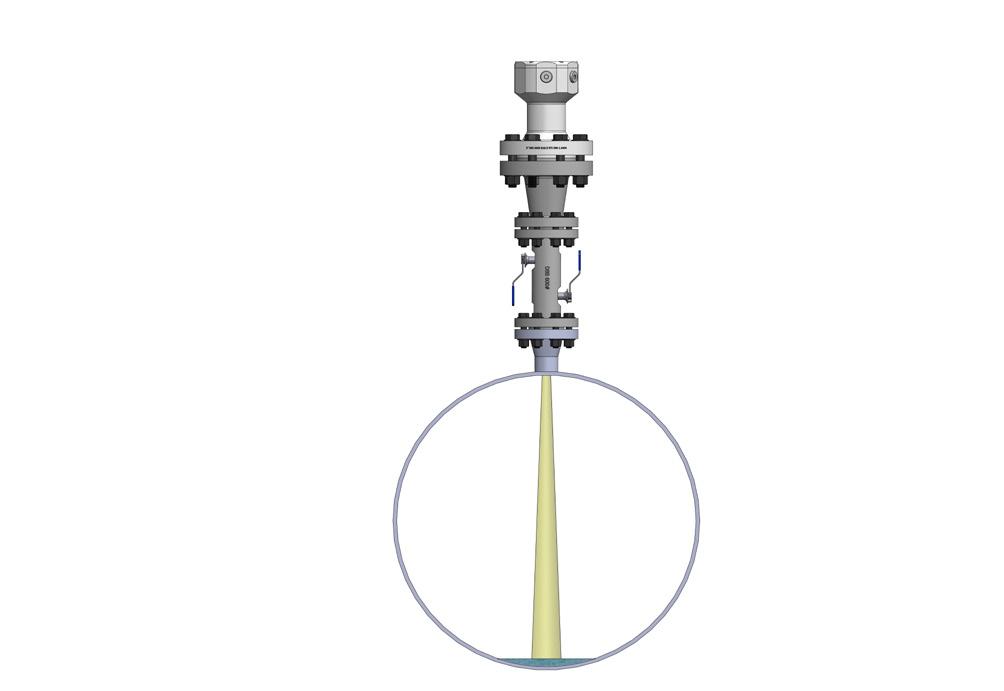
Figure 1. The process camera mounted on the gas pipeline.
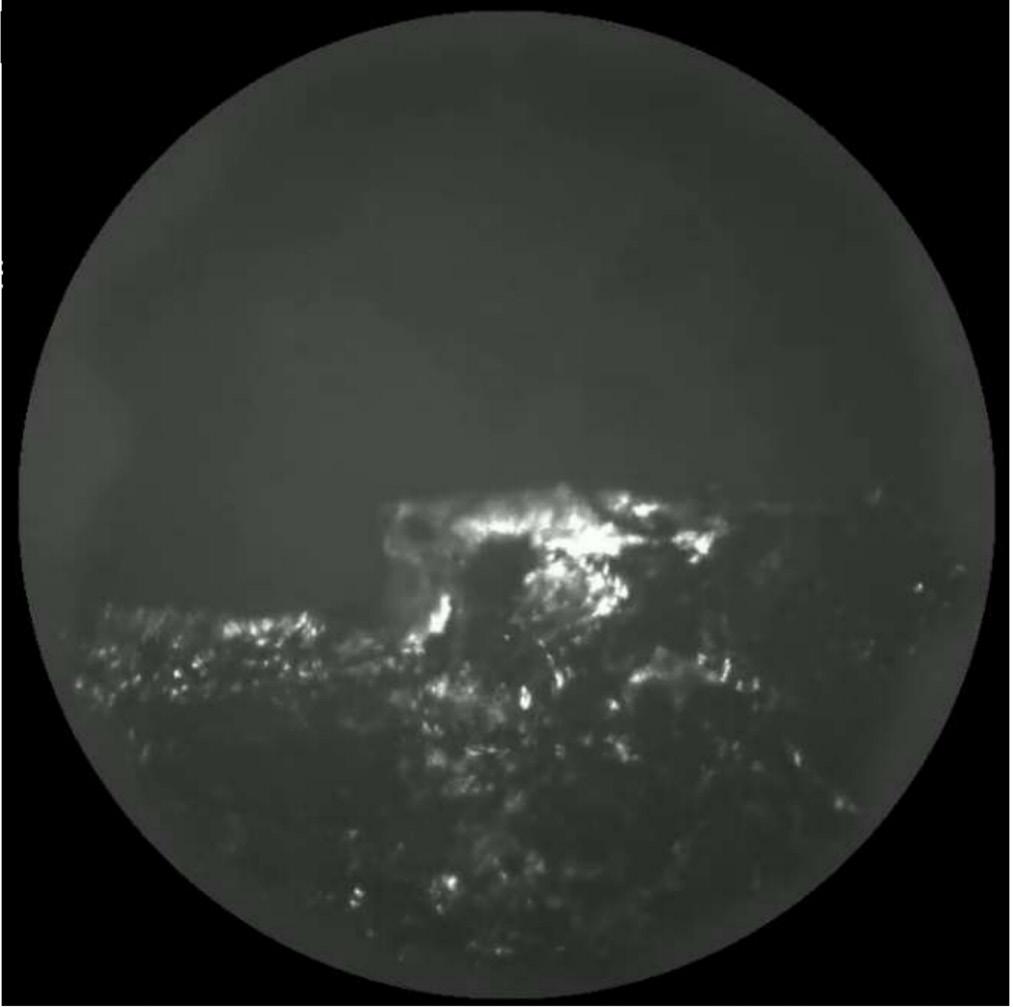
Figure 2. Top left – dry gas. Top right – stratified flow of compressor oil. Bottom left – stratified flow of condensate. Bottom right – mist flow.
10 World Pipelines / APRIL 2024
Figure 3. Grease-like contamination.


into pipeline activity to process managers and technical resources both onsite and remote. They are revealing that liquids are more commonly present than previously thought. This discovery has significant implications for dry gas flow measurement and gas analysis. The cameras are typically mounted vertically and view through an isolation valve, capturing a plan view of the pipeline floor where liquid streams, solids, and mist flows can be observed (Figure 1).
The live-streamed video feeds into control rooms often indicate the presence of liquid streams even when no other alarms have been activated. The metadata from these videos, such as variations in brightness, can serve as useful indicators for the stability of gas flow and can be used to set alarm thresholds. Advanced machine learning techniques further refine the alarm system by categorising the severity of incidents.
Examples of contaminated gas flows
Observations in real-world large diameter gas pipelines with a pressure of around 920 psi have revealed various types of contamination flows. While dry gas flow, stratified flows of compressor oil and condensate, as well as severe mist flows were observed, it’s crucial to note that stratified and mist flows can occur independently and even simultaneously. Contrary to computational fluid dynamic (CFD) models suggest – indicating stratified flows at low gas velocities and mist flows at high velocities – real-world observations have shown both types of flows occurring at varying velocities.
Various parameters, including temperature, liquid density, liquid viscosity, and pipe surface conditions, significantly affect the movement of contaminants in mixed-phase flows. For instance, a mist flow can turn into a stratified flow if there’s a momentary drop in the gas flow. It is also common to observe mist and stratified flows at the same location, either at different times or occasionally simultaneously.
Diurnal changes
Diurnal changes in mist flow are commonly observed in pipelines, with the mist flow increasing during daytime and decreasing at night. This pattern is highly repeatable and independent of absolute temperature and can even lead to the pipe floor being entirely obscured at peak mist flow.
The presence of these repeatable diurnal changes is believed to indicate that a volatile gas, most likely Natural Gas Liquids (NGLs), is present in the pipeline.
Dry material conveyed in a pipeline
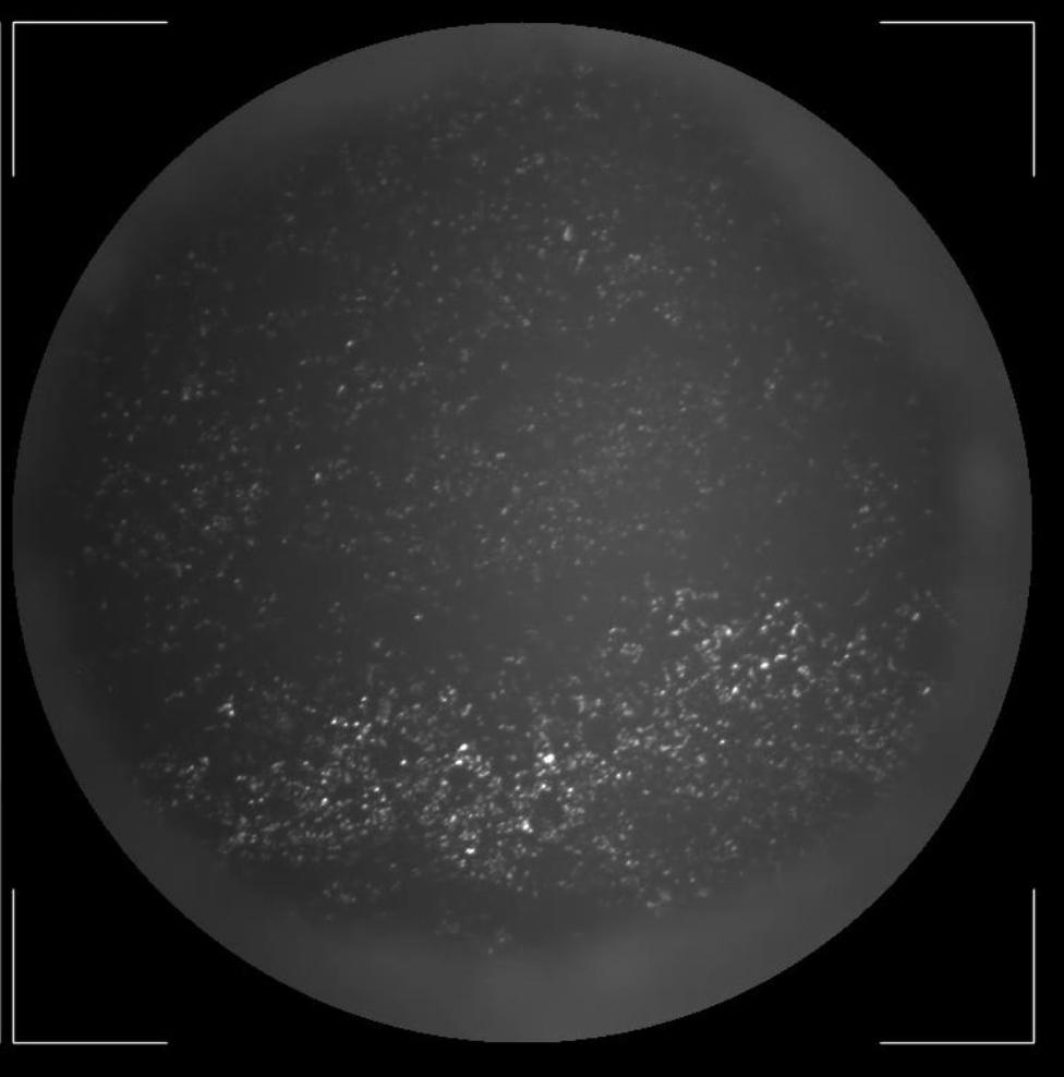
In pipelines, grease-like contaminants (Figure 3) can evolve into dry material once gas flow begins. Over time, the rapid gas flow over these materials dries them out, explaining the presence of dry material when lines are pigged. With stratified flows, liquids within the pipeline are moved along due to friction with the gas. As these liquids move, the quicker-moving gas above them progressively dries out the liquid, leaving the denser and solid content. Eventually, this causes the liquid to slow down and come to a stop, where it continues to dry out, becoming stationary material on the pipeline floor.
Liquid separation within the pipeline
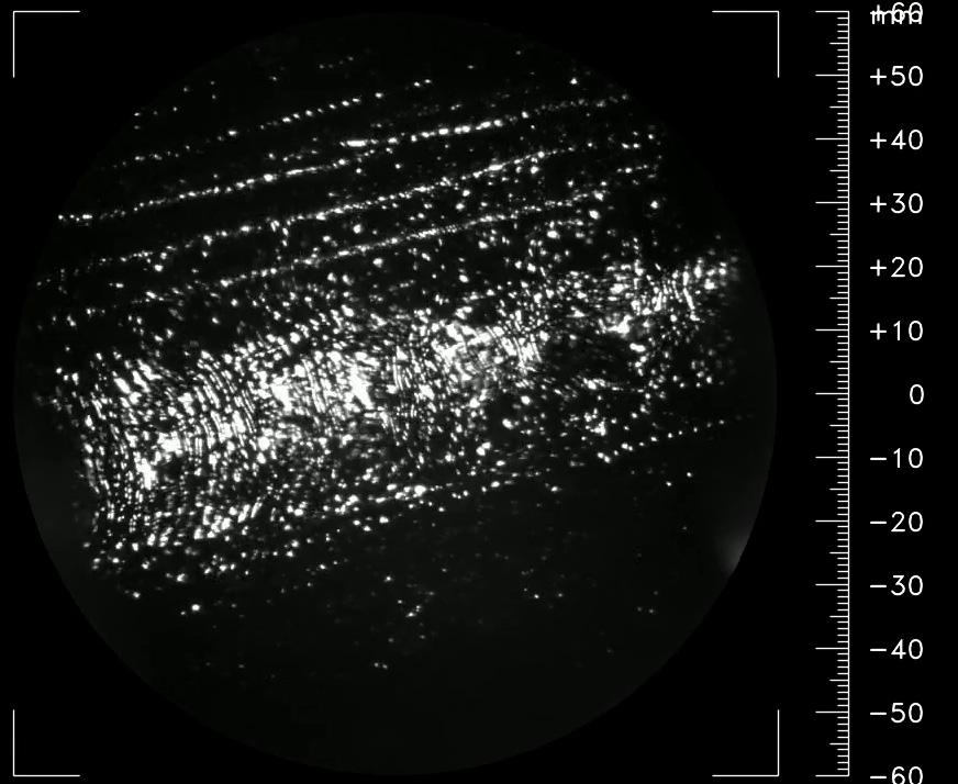
Figure 4 observes a phenomenon in a 36 in. diameter pipeline, showing two stratified flows: a worm-like flow of compressor oil at the top and bottom, and a stream of another liquid in the centre. These liquids of different densities appear to have separated in the pipeline. The gas flow is from left to right, and the liquid flow is angled differently, likely because the installation is near to two 90° bends. This suggests that the twisting gas flow, created by the bends, is influencing the direction of the liquid flow due to friction between the gas and liquid.
Errors in fiscal measurement – calorific value
The importance of accuracy for calorific value measurement and protecting gas chromatographs (GCs) and other gas analysers from liquid contamination is underscored by API 14.1, ISO 10715 and the GPA (Gas Processors Association) data book. These standards recommend the use of stabbing probes or quills for
Figure 4. Duel liquid flow.
12 World Pipelines / APRIL 2024
Figure 5. Material on the pipe floor after a liquid event.
taking gas samples from the middle of the pipeline to avoid wall contamination. Additional membrane or coalescing filters should also be installed between the pipeline’s tapping point and the gas analyser to ensure a representative gas sample and longterm, uninterrupted service is achieved. These precautions have produced major shortcomings:
) Operators remain unaware of wet gas or liquid events in the pipeline. This is problematic as it can result in significant errors in calorific value calculations, sometimes exceeding 40 Btu, during events that can be almost continuous on some flows observed at custody transfer points. This can lead to significant financial losses for the gas producer.
) The standard practice of avoiding and removing any liquids from the sample may produce a false sense of security. Specifically, hydrocarbon (HC) dewpoints calculated from GC data lead operators to believe the gas is much drier than it actually is in the pipeline, leading to higher operational risks of corrosion and compressor failures for transmission system operators.
) Operators are unaware when liquids are present in the pipeline and exceed the gas quality requirements of tariffs and other commercial agreements. This means compliance with gas quality standards is not met.
Installation of process cameras validates the measurements from gas analysers when a single-phase flow is present, and alerts operators to the presence of wet gas or mixed-phase flow, dramatically reducing the uncertainty budget and filling a crucial gap in the current measurement systems to have a more accurate understanding of what’s actually occurring within the gas pipeline.
Errors in fiscal measurements of flow
The Sarbanes-Oxley compliance requires accounting for errors in fiscal flow measurements of natural gas.3 While unexpected liquids events in dry gas systems can significantly inflate the uncertainty budget, it has been observed that these events normally leave behind solid material that has been swept up in the liquid flow. This solid material remains in the flow metering station as a permanent reminder of the liquid event and causes two main issues:
) Dry gas meters can read up to 2% in error when liquids are present. A process camera can confirm single-phase gas flow.
) Solids carried by liquid flows can accumulate on the pipeline floor, reducing its diameter in metering stations, just a small depth (<1/8 in.) can result in 0.3% errors, which is significant given the overall fiscal measurement uncertainty target of <0.5%.
These factors highlight the need for regular visual inspections and make them crucial for accurate fiscal measurements.
Cost of pigging and disposal of contaminants
Traditional pigging costs for a 30 mile section can range between US$2.5 million - 3.3 million, making it a costly and risky operation.
Using process cameras to monitor contamination ingress can reduce the risks associated with pigging and optimise its frequency. This can also lead to reduced methane emissions from venting at the pig launcher and receiver.
Pipeline corrosion
Internal corrosion
Liquid accumulation in pipelines poses a significant risk of internal corrosion, which can lead to catastrophic incidents such as pipeline ruptures. An example of this was the Carlsbad, NM incident, caused by the failure of a ‘drip’ separator designed to collect stratified flows of liquid.4 In this case, solid material had also been conveyed by the liquid and accumulated, blocking 80% of the cross-sectional area. This led to further liquid accumulation in the pipeline and ultimately to significant internal corrosion that caused a rupture and a fatal incident. Monitoring pipelines for liquid carry-over is crucial for identifying risks such as mist or stratified flows, which cause such failures.
External corrosion
Underground pipelines are commonly safeguarded against external corrosion through cathodic protection (CP) systems. These systems use a small DC voltage between the underground pipe and a sacrificial anode. An isolating joint separates the underground and above-ground sections to ensure the system’s effectiveness. However, the presence of contamination in the pipeline breaches this isolating joint. Being electrically conductive, these solids compromise the effectiveness of the CP system, increasing the risk of corrosion for the pipeline.
Conclusion
In summary, there are critical gaps in the traditional methods for monitoring and managing gas flows, particularly in detecting liquid carryover. The cost of these gaps is immense, with failures leading to losses ranging from US$250 000 - 250 million, as indicated by surveys from Amine Experts and the UK Health and Safety Executive.1,2 These shortcomings impact not just fiscal measurements but also operational efficiency and safety, including compressor damage and pipeline corrosion.
The use of process cameras are emerging as a gamechanging technology that provides real-time visual insights into pipeline activity, revealing issues like phase separator and filter performance that would otherwise go unnoticed. These cameras offer a solution to multiple challenges – from validating metrics like calorific value and flow to alerting operators of conditions that may result in costly failures or breach API and ISO standards. By filling these gaps, process cameras not only mitigate financial risks but also enhance operational efficiency, safety and asset integrity.
References
1. Trends in Tragedy – An in-depth study of Amine system failures, Amine Experts.
2. Hydrocarbon Release – dry gas seal integrity survey report – Offshore Technology Report 2000/070.
3. Gas Measurement Has Key Role In Sarbanes-Oxley Law Compliance, Tim Nesler, EMS Pipeline Services, Houston, TX.
4. Pipeline Accident Report Natural Gas Pipeline Rupture and Fire Near Carlsbad, New Mexico 19 August 2000.
14 World Pipelines / APRIL 2024

Phanindra Kanakamedala and Greg Morrow, Emerson, USA, consider leak detection, risk mitigation and tightening regulatory environments.
With the industry’s ever-tightening leak detection and rupture mitigation requirements, regulators are recommending the use of advanced technologies for oil and gas companies to manage their operations safely and profitably. The risks of not having critical data when needed are becoming too great for operators of gas and liquid pipelines and storage facilities.
The latest round of PHMSA’s ‘Mega’ rulings is only one part of a new regulatory landscape unfolding in the US and globally. The emphasis now is on the continuous monitoring of pipeline integrity, and facilitating early detection of anomalies that could indicate a leak or the potential for rupture.
Leak detection and pipe
Occurrences of leaks and major ruptures are rare, as pipeline systems and networks remain the safest, most economically sound method of transporting energy resources. Historically, leak detection and containment were not as high of a priority for some gas distribution, transmission and gathering pipelines, and hazardous liquid pipelines, as they were being developed.
Earlier pipeline systems were built according to the standards of their time, with more or less robust safety measures. Most of those systems have made marked improvement in safety measures –particularly liquid pipelines – undergoing retrofitting and upgrades to improve safety and comply with regulations. As high-consequence areas (HCAs) have been redefined and expanded, more and more pipelines need to meet higher standards to achieve safety, match industry best practices, and meet regulatory requirements.
‘Mega’ prism: gaps in leak detection
PHMSA stipulations impact many US onshore gas transmission and hazardous liquid pipelines, regardless of size or location. Safety and reporting requirements now extend to more than 400 000 miles of
15
Figure 1. Population centres worldwide have been built on top of existing gas pipeline networks, creating a series of high consequence areas (HCAs) that require continuous monitoring.
gas gathering lines. Of note are the tens of thousands of miles of previously unregulated pipe under federal governance.
The federal agency’s management of change (MOC) definitions have been broadened concerning “significant changes that pose a risk to safety or the environment.” This type of regulatory vocabulary can be viewed as a prism for contemporary alignment, reflecting growing concerns around pipeline integrity management and safeguarding population centres, as well as ties to public perception, reputation management, and the clean energy future paradigm.
Industrial manufacturers such as Emerson have been developing technologies to satisfy legal requirements and corporate responsibilities, exceeding mandates for current leak and rupture detection, and addressing pipeline operators’ needs through these evolving lenses. A highly collaborative effort between manufacturers and end users is paramount to ensure technologies remain aligned to the latest industry requirements.
The international governing bodies tend to take cues from American-recommended practices with NTSB, API and GPSA standards often being a measure applied for many companies. Gas pipeline operators are anticipating accelerated growth in regulatory activities and strict non-compliance penalties on both state and federal levels. This is occurring in tandem with a global emphasis on emission reductions and emerging opportunities in the hydrogen and carbon dioxide pipeline market sectors.
All the new rules and their ramifications are providing a global forum for proactive dialogue that centres on addressing the leak detection and mitigation valve installation needs and challenges. It is becoming clear that leak and rupture detection technology guidelines on state and regional platforms could exceed federal requirements, and there is room for greater collaboration to identify the potential for any gaps head-on.
A new degree of urgency
Any high-pressure or volatile fluid could, and should, be contained and regulated to the right degree. The Mega Rule and the probability of future pipeline legislation add a new sense of sense of urgency and ‘meat to the bone’.
For some pipeline companies, this involves implementing leak detection systems where they might not have existed before, conducting integrity assessments for the whole pipeline, and enhancing emergency response plans for entire or continuous systems. This is particularly true for the clean energy future.
The US federal government is aligning the ongoing leak detection and mitigation conversation squarely with efforts to uphold the public’s trust, at the same time weighing the cost and benefits around the proposed new development of critical oil and gas pipelines and blended energy infrastructures.
As repair mandates are determined by leak severity with requirements for operators to act quickly to protect people and mitigate the release of emissions, the rules additionally provide latitude and options for pipeline companies to implement innovative and readily available technologies.
A 1Q24 written testimony of a PHMSA deputy administrator before the US House of Representatives Committee on Energy and Commerce reflects how the government is doubling down on the regulatory and environmental perspectives. Accessing leak detection and rupture mitigation capabilities amid new energy
transportation and product storage infrastructure solutions on the horizon are being unambiguously identified as a critical link:
“The Notice of Proposed Rulemaking (NPRM) updates decades-old, federal leak detection and repair standards are in favour of new requirements that add an additional layer of safety by deploying commercially available, advanced technologies to find and fix gas leaks that previously may have gone unrepaired in perpetuity.”
New leak detection enforcement mode
In 1Q24, PHMSA was tracking a dozen active hydrogen pipeline research projects, reflecting approximately US$11 million in research investments. The concern is how to safely transport and store hydrogen and hydrogen blends by repurposing existing infrastructure used for natural gas transport and underground storage and improving hydrogen leak detection.
At least four projects were actively being used for the determination of impact areas related to the safe operation of CO2 pipelines, including the probable impact radius for carbon dioxide, innovative leak detection methods, material testing and qualification for repurposing pipelines and underground storage facilities for CO2 transport and storage.
PHMSA, citing its investigation and enforcement activities involving the 2020 pipeline rupture in Satartia, MS, has made CO2 pipeline regulation a top priority, noting an intention to issue a Carbon Dioxide and Hazardous Liquid Pipeline Safety NPRM this year. This incident in Mississippi has opened another door for government intervention to ensure compliance with industry best practices, similar to the 2010 San Bruno, CA natural gas and Marshall, MI crude oil pipeline events, which ultimately became trigger points for some NTSB recommendations now being implemented.
In 2021, 2022 and 2023, PHMSA announced that it set records and last year alone issued over US$12.5 million in proposed civil penalties against operators who did not comply with safety regulations.
Moreover, on the state level, with Colorado as just one example, they appear to be following suit on stern regulations and strict penalties for gas pipeline operators on leak disclosures and line locations. It was reported that new rules in the state were set to double the maximum civil penalty per violation to US$200 000 for non-compliance.
Faster response, complete isolation
Among notable Mega Rule provisions are requirements for identifying pressure loss and the need for rapid response to gas pipeline ruptures and leaks. The rules specify criteria for the installation of remote-control or automatic shutoff valves, or equivalent technology, at strategic locations and other requirements to ensure affected gas pipeline sections can be completely isolated.
Operators are required to identify ruptures – and close valves to isolate the ruptured segment as soon as practicable –not exceeding 30 minutes from rupture identification. Criteria and levels of complexity differ and may include situations where there are unexplained liquid or gas flowrate changes due to an equipment function, any large release of gas, a fire or explosion in the near vicinity of the pipeline, amid other variables.
16 World Pipelines / APRIL 2024
IT IS MY DEDICATED PASSION
for pipelines that compels me to partner with others in the industry, share best practices and collaborate on ideas for future innovations and advanced applications.
It is who I am. I am a pipeliner.
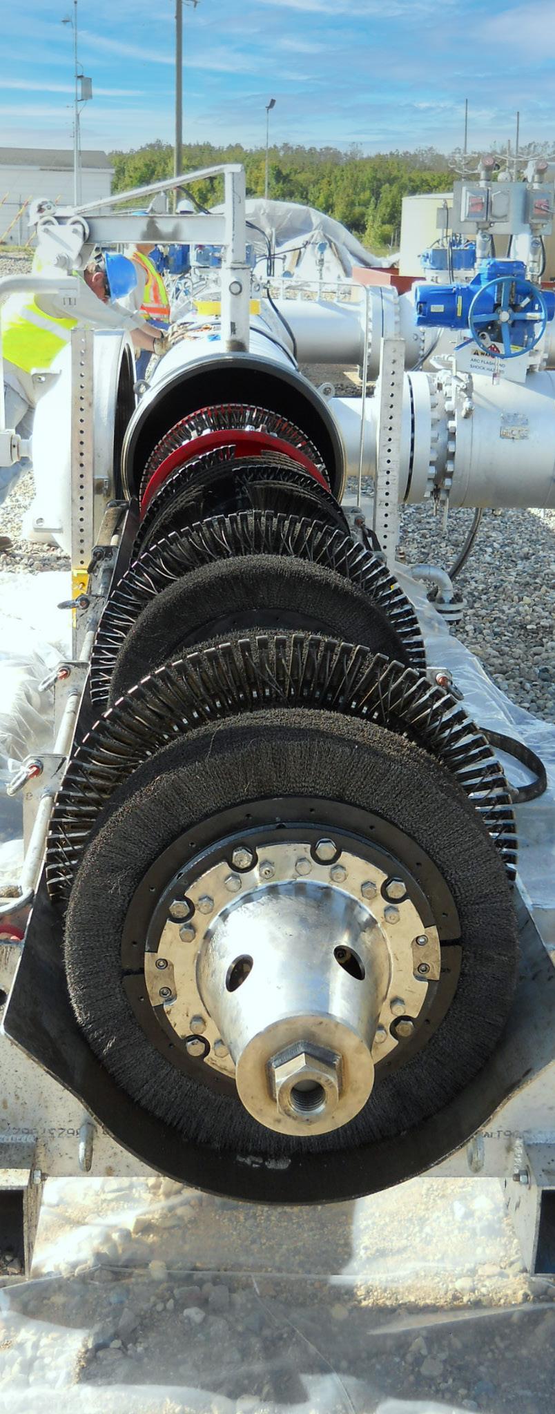
We are pipeliners too.
We share this passion and, like you, we are committed to keeping pipelines running safely and reliably. By providing top-of-the-line tools to address your threats, and applying the most advanced assessment techniques, we ensure you get the best return on your pipeline asset, both economically and environmentally.
The world counts on you. You can count on us.

Coming to PTC?
Stop by and see us at stand C14
Scan here for a preview of our presentations and more info about our show presence.
T.D. Williamson
©2024
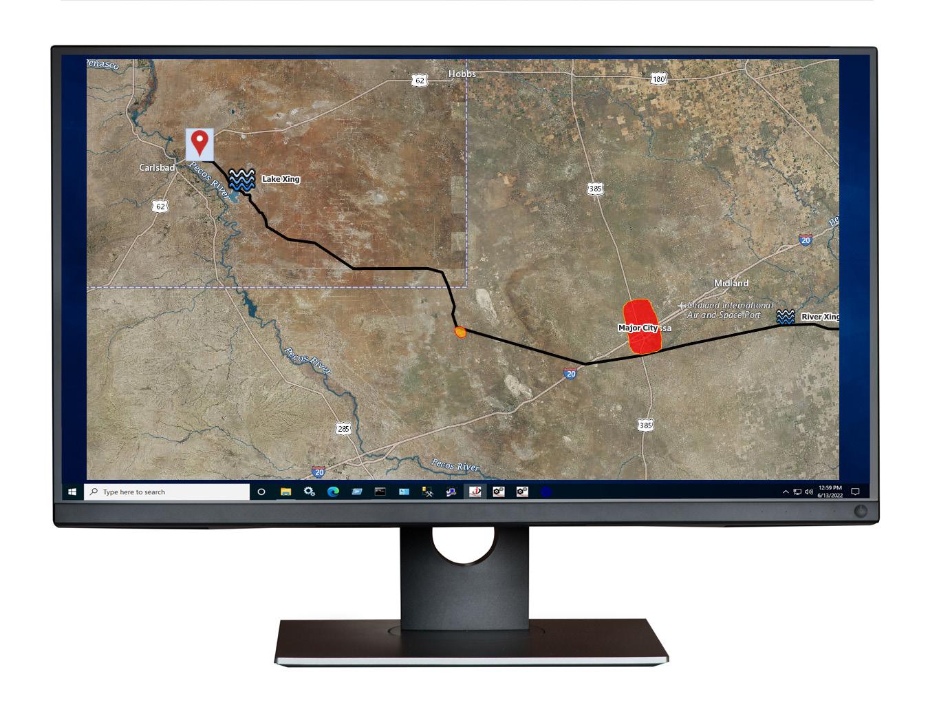
Is it limited to one location? Are multiple locations impacted? Is it an outage situation? How can leaks be detected and locations pinpointed more strategically and effectively, expediting a response to mitigate the impact of pipeline ruptures?
Among the primary concerns is what’s next on the horizon for monitoring and detecting leaks and mitigating ruptures. How many rupture-mitigation valves (RMVs) are necessary? What factors must be considered when determining where and how far apart they should be located?
Leak surveillance, penalties for oversight Strides have been made in technologies linked to strategies for recurrent leak surveillance, including how government access to satellite imagery could be readily available and used by regulatory bodies to monitor occurrences such as venting, unlit flares, and emergency release scenarios.
If a leak goes undetected between a company’s internal inspection milestones but picked up sooner by regulatory monitors, this can translate into heftier fines, and more cumulative penalisation. If an opportunity to proactively discover and more cost-effectively remediate a leak event is missed, they could be fined for the entire assumed duration of the leak. This is just one example of a regulatory occurrence that the use of the right leak monitoring technology could prevent or fix.
On the other end of the spectrum, pipeline ruptures require rapid response to protect lives, assets, and the environment, and limit impacts, while doing everything possible to maintain the public’s trust. If a breach occurs, the technology must accurately and reliably recognise it to ensure pipeline controllers can take confident action to rapidly remediate the situation.
The right detection, actual localisation Technology manufacturers are responsible for consistently emphasising the ability to detect and locate, leveraging sophisticated methodologies for identifying and analysing leaks and ruptures. The components and applications vary by oil and gas company, individual specifications, and requirements. One pivot point hinges on the ability of actual leaks or ruptures, not false alarms, to be discovered.
This must allow for operators to be alerted quickly so that a proper response can be facilitated before leaks result in stiffer penalties or situational unmanageability grows. Emerson’s PipelineManager software enables rapid detection and high sensitivity to both large and pinhole-sized leaks through statistical analysis and filtering techniques. These advanced capabilities enable companies to achieve more immediate and cost-effective remediation as any leaks can be identified and localised, faster.
Methods of leak, rupture detection effectiveness
Different methodologies for leak detection include those based on volume or mass balance versus direct instrument monitoring. PipelineManager software utilises both modelbased and non-model-based methods. This allows for the selection of the most appropriate technique based on engineering assessments.
The software offers advanced data reception and processing capabilities. Data are integrated from various sources such as flowmeters, pressure sensors, and temperature gauges, to construct a comprehensive real-time picture of pipeline operations. This integration allows for the continuous monitoring of pipeline integrity, facilitating early detection of anomalies that could indicate a leak.
PipelineManager software enhances rupture detection by analysing deviations in flow and pressure measurements, ensuring accurate identification under various operational modes such as pressure control, flow-control, shut-in, or slack conditions. Model-based methods are highlighted for enabling fast and accurate leak detection even in transient conditions. These methods are robust across various operational scenarios – used for low flowrate and product theft scenarios to enhancing rupture mitigation efforts.
PipelineManager software is based on modelling technology that provides pipeline leak detection and localisation, batch composition tracking, automated forecasting, facility planning and operator training, as well as multiple leak detection technologies to detect ruptures.
Deviation analysis and sophisticated statistical evaluation is employed by PipelineManager to differentiate rupture signatures from normal operational changes. Moreover, the software’s MAOP monitoring ensures operations do not exceed the safety limits for pressure, critical for preventing incidents. Built-in features enhance safety and operational efficiency via real-time data and alerts for critical parameters.
Operators can generate reports that are shared with authorities, satisfying auditing needs and demonstrating compliance with regulatory requirements. Real-time progression of corrosion and erosion monitoring from anywhere, and longdistance pipeline monitoring can also be set up.
A meaningful response
An integral piece of PipelineManager software is tied to improving alarm reliability and increasing operator confidence in an appropriate and meaningful response. The quality of input data here is central. Inconsistencies can result in more frequent false positive alarms, with operator fatigue and the potential for control room complacency both at stake.
18 World Pipelines / APRIL 2024
Figure 2. Advanced software with GIS capabilities provides control room operators with a clear view of a potential leak point.


HOW ABOUT A COATING WITH A 60 YEAR LIFETIME?

STOPAQ is a purpose designed sustainable coating solution in order to comply with our future reality.
The technology behind STOPAQ is referred to as visco-elastic. However, viscoelasticity is the behaviour of the polymer used.
STOPAQ is at heart a Polyisobutene (PIB) based coating. This polymer creates an impermeable barrier to oxygen and water and doesn’t cure over time. This leads to permanent adhesion to the surface, resulting in an extended lifetime of the coating and permanent corrosion prevention of the asset.


Designing coating solutions for a maintenance-free future.

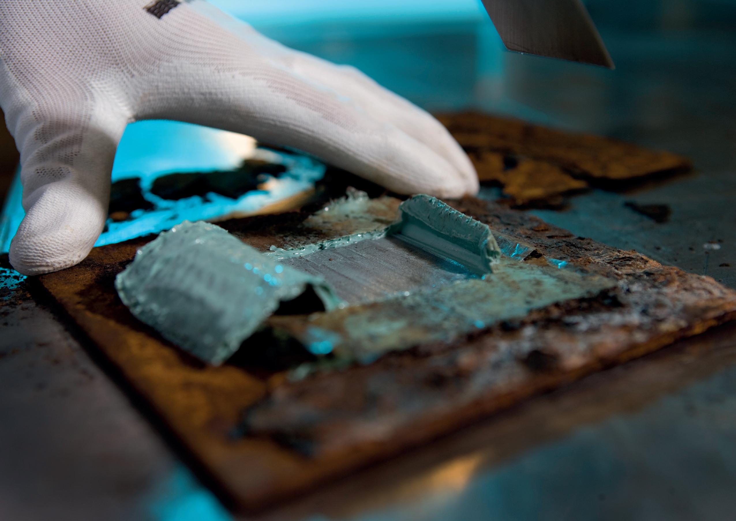

Learn from the past Think of the future Learn all about our solutions and their maintenance benefits in our new podcast series: www.stopaq.com/news
Self Healing Corrosion Prevention & Sealant Technology
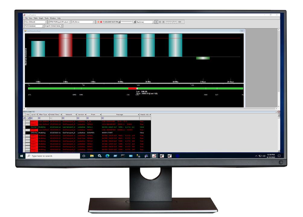
Leak detection, risk mitigation
Pipeline companies stand at a critical juncture, balancing calls for more robust gas pipeline safety and security prerogatives that are in step with emission reduction goals and the ability to meet rising global energy demands. The development of many mainline gas pipelines in the US occurred more than 60, or even 80, years ago. A few Civil War-era gas distribution segments still exist – that’s over 150 years in the ground.
The selection of the appropriate methodology is more of an engineering assessment, considering performance criteria, cost and instrument availability rather than a proving exercise for a particular leak detection technology.
The aim is always to ensure that leaks are discovered and repaired before they can degrade into more serious ruptures.
Overcoming future leak detection complexity
PipelineManager software enables pipeline companies to sustain high-performance levels with its demonstrated ability to be highly effective in detecting leaks incisively and with minimal false alarms. It can alert on ruptures during events that typically hinder other systems, like pump trips and flow starts. It also reduces sensitivity to transient effects and adapts to various conditions.
It additionally accounts for data from a SCADA system and performs real-time transient modelling using a fully thermodynamic, first principles physical model (a digital twin of the pipeline) to determine if a leak has occurred.
Proposed rulemaking around advanced leak detection programme (ALDP) performance standards and requirements underscore realities, bringing those associated with establishing minimum standards for evaluating criteria for leak grades and repair schedules that much nearer. There will be vital impacts as they decide how to approach regulations with natural gas, hydrogen and CO2 pipes each at the forefront of a safe and clean energy transition narrative.
When it comes to peeling back layers to identify any potential gaps in strategic leak detection and rupture mitigation strategy and the implementation of an optimal technology, proactive action is the greatest shield against ambiguity or uncertainty.

www.iploca.com/events
2024 SORRENTO, ITALY
Figure 3. Emerson’s PipelineManager software uses statistical analysis and filtering techniques to ensure leaks can be quickly identified and localised.
9-13 September
EVALUATION OF GROWING CORROSION
Fadillah Syahputra, Zugao Chen and Tim Zhang, Deyuan Pipeline Technology Co., Ltd, China, describe detecting internal corrosion
defects through eddy current inline inspection technology across China’s W shale
gas field pipelines.
In the challenging terrains of Southwest China’s W shale gas field, several natural gas gathering pipelines ranging from 8 in. - 20 in. were constructed with significant elevation changes and numerous bends, with a minimum bend radius of 1.5D. The medium inside these pipelines, comprising water-bearing shale gas, introduces internal corrosion as a fundamental challenge to the gas field’s pipeline system. It is well known that microbiologically influenced corrosion (MIC) and CO2 corrosion are the common types of corrosion in shale gas fields. To ensure the safe operation of shale gas pipelines, it is crucial to monitor the trend of internal corrosion growth, understand the corrosion growth rate, and assess the effectiveness of existing corrosion control measures.
Over 70% of the pipelines in this gas field are equipped with pigging valves for launching pipeline cleaning devices, such as foam pigs and mandrel pigs with or without wire brush. With the given low daily gas throughput in some pipelines, selecting internal inspection technologies compatible with pigging valves presents a challenge for the pipeline inspection engineers. The PIGPROX inline inspection (ILI) technology utilises patented eddy current sensor technology. This ILI technology is specifically designed for detecting internal corrosion defects. The PIGPROX design resembles that of a cleaning pig, characterised by its short length, light weight, and flexible navigability, making it compatible with pigging valves for easy deployment.
21
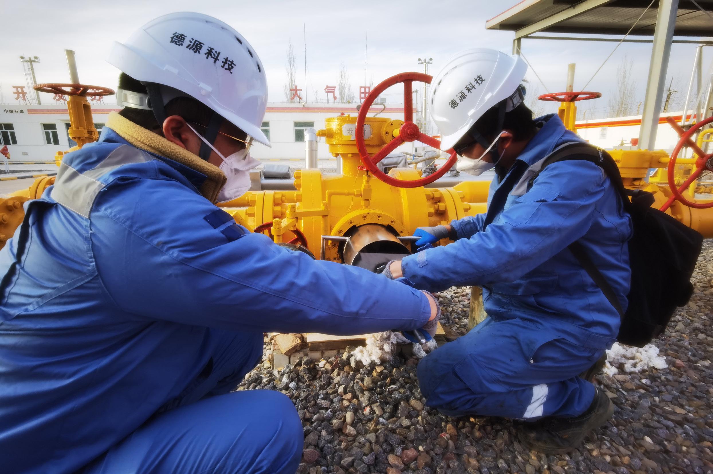
Figure 1. PIGPROX eddy current tool launch via pig valve.


PIGPROX ILI operation
The five shale gas lines shown in Table 1 were inspected two times by PIGPROX ILI tools in 2022 and 2023.
Among these five shale gas pipelines, three pipelines utilised pigging valves for launching, whilst the other two pipelines utilised the standard pig launching barrels. The pipeline with the highest average operational velocity reaches
up to 3 m/sec., whereas the slowest operates at 0.48 m/sec. The inspection was successfully conducted on all these pipelines, with the first run success rate of 100% and collected good quality data of high signal to noise ratio.
ILI data outcome in 2022 and 2023
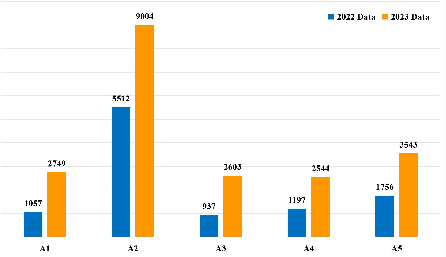
Number of defects analysis
The number of internal corrosions detected in 2023 indicated a significant increase, with the growth of new defects ranging between 63.4% and 177.8%. This phenomenon highlights that the growth of internal corrosions has escalated on these inspected pipelines.
Startling internal corrosion growth
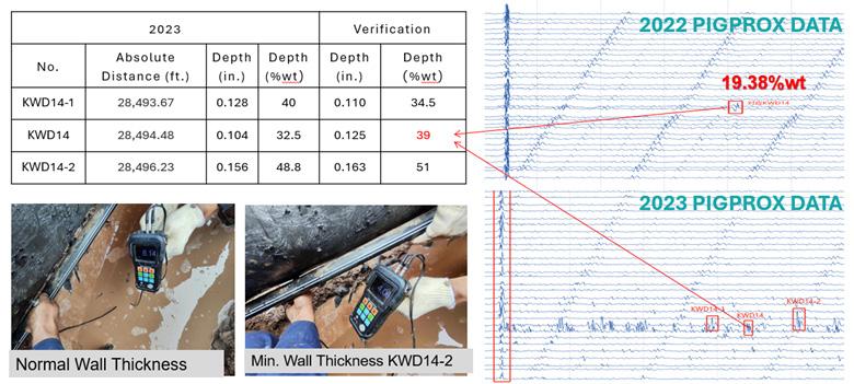
Taking A2 pipeline as an example, we did a run comparison of the PIGPROX eddy current inspection data between 2022 and 2023. The analysed data in 2022 and 2023 revealed a significant finding at the distance of 8685.118 m. The result of the PIGPROX inspection in 2022 identified a defect with a depth of 19.28% wt, which, by the 2023 inspection, had grown to 32.5% wt. Upon excavation activities, the actual measured depth of the defect was verified to be 39% wt, indicating nearly a 20% wt increase in depth. In addition to the existing internal corrosion growth, a number of new defects were detected and identified near this location in the 2023 inspection. For example, the internal corrosion at the 8685.651 m mark was a new defect but it had reached a depth of 51% wt, as detailed in Figure 5.
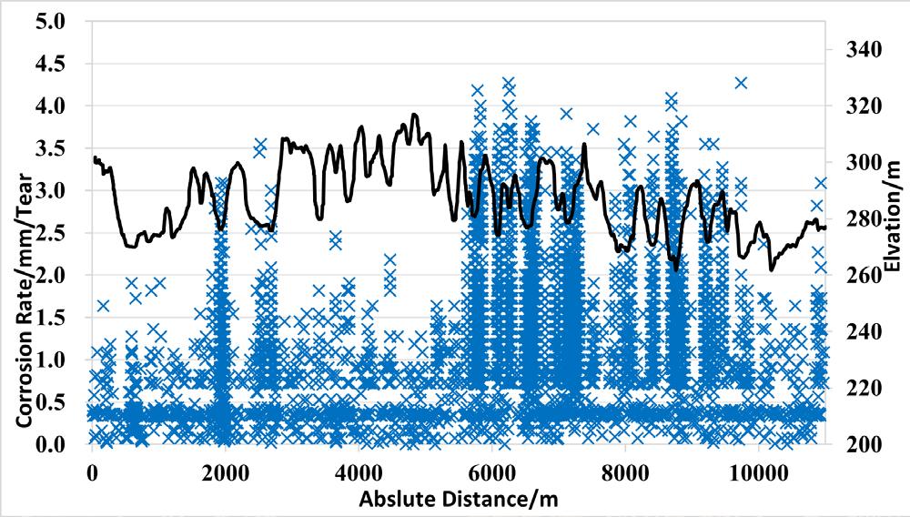
Internal corrosion and pipeline elevation analysis
The growth of internal corrosion in these five pipelines is closely linked to the accumulation of residual fluids from the existing transported product, exemplified by the A2 pipeline. An overlay and alignment analysis of internal corrosion defects with the pipeline’s elevation (as detailed in Figure 5) reveals that:
) Internal corrosion defects show a significant concentration trend at the lower elevation sections and uphill liquidholding segments of the pipeline.
) The internal corrosion growth trend within these low-lying areas and uphill liquid-holding segments is pronounced, with a faster growth rate compared to other sections of the pipeline, as evidenced by a comparison of inspection data from 2022 and 2023 (Figure 6 gives detailed analysis).
By integrating internal corrosion defect data with elevation data, an in-depth analysis of the pipelines of W gas field were performed and it was emphasised that the tendency for residual product accumulation is higher in low elevation sections and orientation, between the 4:00 and 8:00 positions. This localised accumulation fosters a conducive environment for the proliferation of microbial and bacterial colonies, significantly contributing to the accelerated progression of internal corrosion growth within these segments.
Figure 2. Internal corrosion defects located at the spiral weld zones.
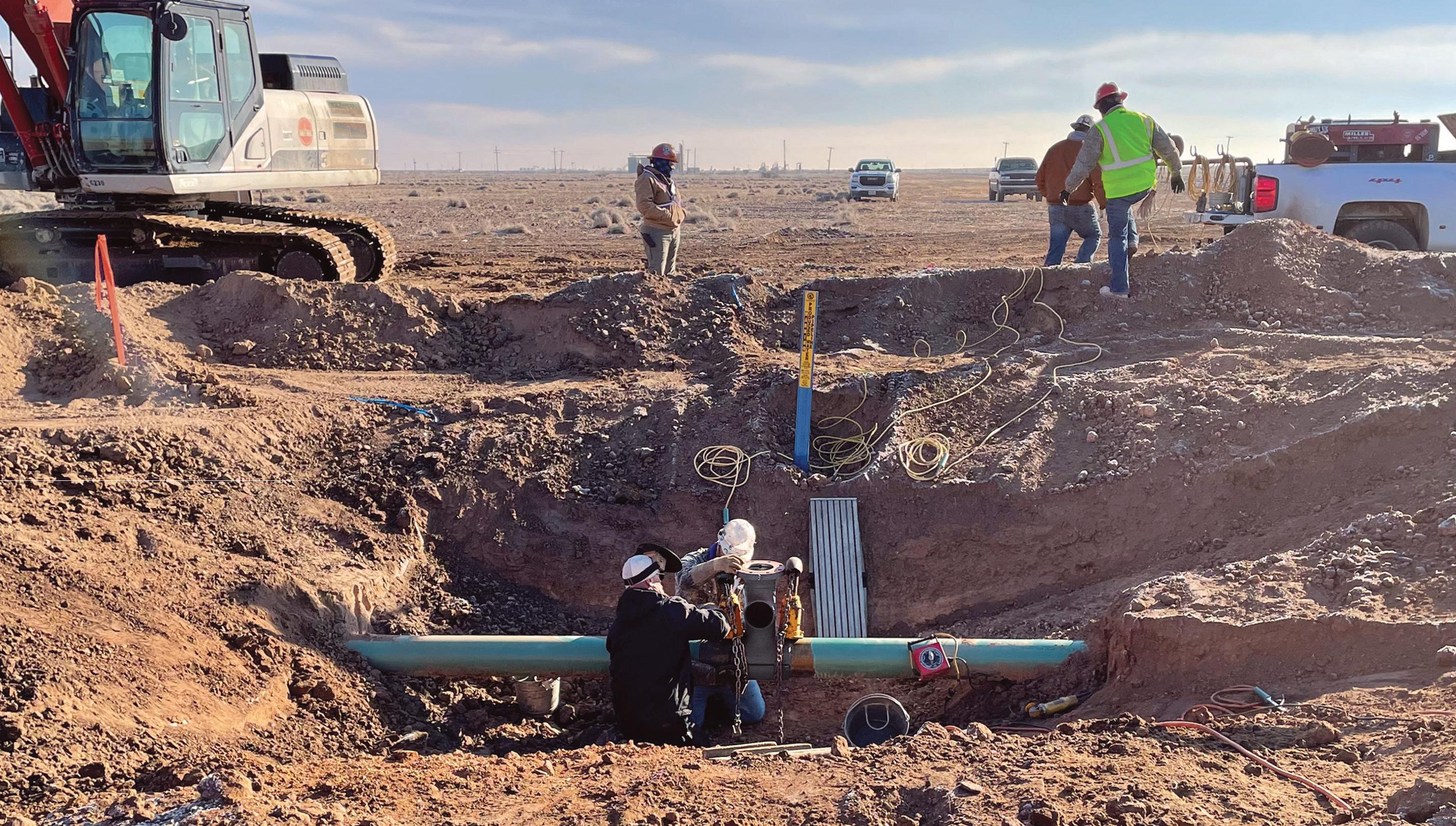
Figure 3. PIGPROX site operation.
Figure 4. Statistics chart of defects in 2022 and 2023.
Name Outside diameter Wall thickness Length 2022 inspection date 2023 inspection date ILI days interval A1 10 in. 0.279 in. 3.50 miles 6 July 2022 24 November 2023 506 A2 12 in. 0.312 in. 6.86 miles 7 October 2022 29 November 2023 418 A3 12 in. 0.312 in. 5.81 miles 3 October 2022 23 November 2023 416 A4 10 in. 0.279 in. 2.93 miles 6 July 2022 22 November 2023 504 A5 20 in. 0.438 in. 3.1 miles 22 July 2022 29 November 2023 495 22 World Pipelines / APRIL 2024
Table 1. Inspection dates of 2022 and 2023


There’s nothing quite like welding onto a live pipeline In this high-stakes operation, product flow affects heating and cooling, making proper planning and execution a must. Without it, your pipeline’s long-term integrity is at risk.
WeldFit’s API 1104-qualified welders average a decade in the industry, so they get the job done right. And they’re backed by simulation and real-world testing, ensuring they’re following the most appropriate procedures to reduce pipeline threats. When it’s not just another weld, choose WeldFit. Contact your WeldFit representative to learn more.
WeldFit.com/ISW
TM Trademark of WeldFit Corporation in the United States and other countries. © Copyright 2024 All rights reserved by WeldFit Corporation
ANOTHER
For In-Service Welding, Expertise Matters. Qualified / Reliable / Safe
NOT JUST
WELD.


Circumferential distribution of internal corrosion
Figure 9 shows the orientation of the internal corrosion distributed from 4:00 to 8:00.
To summarise
Throughout 2022 and 2023, the extensive application of PIGPROX eddy current inspection technology in the W shale gas field’s gathering pipelines yielded some significant data to clients on the growth of the internal corrosion defects. Integrity engineers have analysed this data and, in response, they have enhanced the safety and operational integrity of the pipelines by increasing pigging frequency, selecting more effective corrosion inhibitors, and finetuning microbial corrosion control strategies. These adjustments have effectively slowed down the progression of internal corrosion. Since the implementation of the PIGPROX internal inspection in the shale gas field in 2022, there have been no occurrences of pipeline failures or gas leaks caused by internal corrosion. PIGPROX ILI technology has provided the scientific and test results to ensure its safe operation.
PIGPROX eddy current ILI technology has proven to be indispensable in inspecting pipelines with low flow and low pressure, as well as those pipelines which are equipped with pigging valves. It delivers the quality of the collected data by providing accurate, efficient internal inspection capabilities, and pioneering solutions for pipeline integrity management system.
Future directions
The widespread deployment and detailed examination of the PIGPROX eddy current ILI technology across the W shale gas field’s collection pipelines have yielded an abundance of insights, significantly enhancing pipeline integrity management strategies. As the oil and gas sector confronts the everincreasing complexities and challenges in ensuring pipeline integrity within such demanding environments.
The innovative technologies like PIGPROX provide not only effective solutions for ensuring the safety and efficiency of pipeline operations but also it becomes a foundation of ongoing advancements in the field. The emphasis of inspection technologies is expected to shift towards better technological innovations, more sophisticated yet efficient data analytics capabilities, and more cohesive pipeline integrity management frameworks.
These advancements aim to tackle the dynamic challenges associated with pipeline corrosion and overall integrity management. Enhanced data analytics, in particular, will play a pivotal role in this evolution, offering deeper insights into corrosion patterns, pipeline wear and tear, and potential failure points. This, combined with integrated integrity management systems, promises a more proactive approach to maintaining pipeline health, optimising maintenance schedules, and minimising the risk of unscheduled downtimes or catastrophic failures. Such technological and methodological advancements are essential for the oil and gas industry to adapt to the increasing pressures of environmental sustainability, regulatory compliance, and operational excellence in a landscape marked by rapid technological evolution and heightened global competition.
Figure 5. The No. KWD14 defect growth.
Figure 6. Absolute distance, corrosion rate and elevation distribution diagram.
Figure 7. Comparison and elevation distribution of inspection defects in two rounds of A2 line.
24 World Pipelines / APRIL 2024
Figure 8. Circumferential distribution of internal corrosion of A2 line.
Simon Bell, iNPIPE PRODUCTS, UK, discusses acoustic reflectometry technology as an interesting remote technique to detect full or partial blockages within a live gas pipeline or an empty pipeline during construction.

Inspection of pipelines and the development of various technologies goes back to the 1950s and early 1960s with regard to metal loss, corrosion and crack detection which are widely accepted as areas of most concern. Metal loss surveys broadly fall into three basic methodologies including magnetic flux leakage, ultrasonics and eddy currents, which are typically carried through the pipeline as sophisticated pigs.
The overall diameter of the pipeline is equally important to understand as deposition may occur in various tipping points over the lifetime of the asset.
25

Product flow and chemical makeup may vary over time, which may also have an influence on temperature, and lead to unwanted depositions within the pipeline. Similarly, the effective operation of valves may also be impacted upon over time and there is always the potential for accidental mechanical damage to be considered.
Pipeline blockage detection system
Acoustic reflectometry technology has developed into an interesting remote technique to detect full or partial blockages or obstructions within a live gas pipeline or indeed, simply an empty pipeline during construction. The apparatus is simple to use, easily transportable and quick and easy to connect, typically through an existing 0.5 in. connection. This means that it can be mobilised in a short space of time when the need arises; there is no disruption to gas flow or normal production operations and complex pipeline networks can be easily accommodated and inspected quickly.
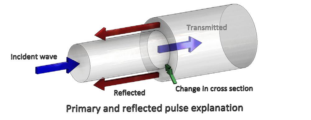
In simple terms, the Acoustek system injects an acoustic pulse, or pressure pulse into the gas pipeline. The pulse travels along the pipeline as a plane wave and any acoustic impedance will partially reflect the pulse. In this way, it is possible to detect reductions in bore potentially caused by mechanical damage or debris build up by measuring the reflections produced; such reflections, together with the knowledge of the speed of sound within the pipeline, allow for the location of feature, such as blockages, holes, valves and buckles, to be accurately detected and located. The technique is totally non-invasive and is equally applicable to small and large diameter pipelines. As the technology is noninvasive it is particularly helpful when used to detect and accurately locate blockages caused by stuck pigs or isolation tools and is accurate to +/- 2.5 m over a 10 km distance. Longer distances can be inspected by disconnecting the equipment and simply moving further down the pipeline and then reconnecting. One of the greatest benefits of the system is that it provides real time, instant analysis which is particularly important in the case of stuck pigs.
Methodology
Ever increasing demand within the global energy market, together with reducing reserve opportunities for onshore or shallow water has led to an international trend towards developing deeper and deeper water reserves. Deep water flow lines across the seabed increase the risk of hydrate formation dramatically and is a major challenge with regard to flow assurance. The oil and gas industry spends a large amount of energy and money in combating the formation of hydrate deposits within natural gas pipelines. It therefore follows that early detection of potentially developing hydrate blockages is very important so that effective remedial actions can be developed and planned.
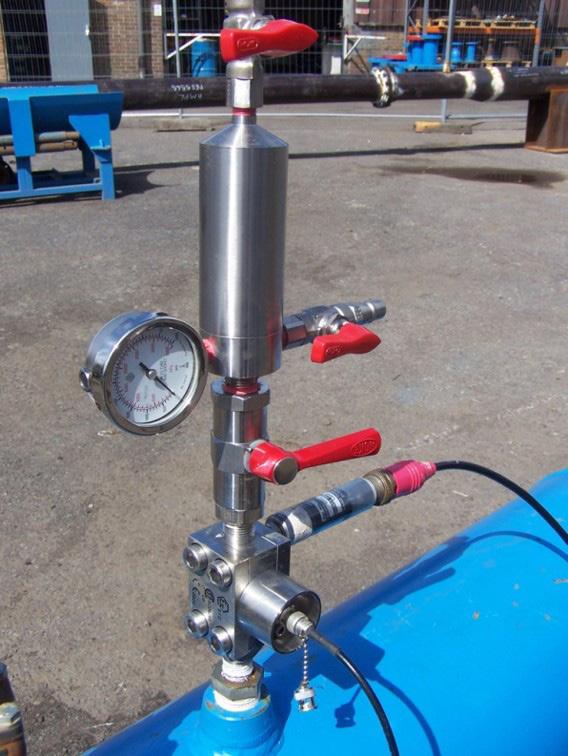
Figure 1. Acoustek blockage detection system connected to the pipeline.
Figure 2. Primary and reflected pulse illustration.
26 World Pipelines / APRIL 2024
Figure 3. Data analysis via laptop software.
Critical to the remedial activities are the location, identification and removal of the obstruction and the accurate evaluation of the blockage is fundamental to the successful completion of this process. Conventional methods traditionally adopted for blockage detection include radiographic methods, flow pressure monitoring detection and diameter expansion methods.
Flow pressure monitoring detection uses pressure wave propagation to remotely detect blockages. A quick acting valve is used to generate a shock wave inside the pipeline and records any reflections generated by any blockage. This method has been proven to detect blockages over long distances with reports of up to 100 km. The speed of sound and potential noise interferences may affect the results and potentially give rise to errors. This method consequently has some limitations as it requires the flow line to be temporarily shut down for a short period of time to create the necessary pressure wave. The pressure wave leads to water hammer upstream of the closing valve together with cavitational hammer downstream of the valve which may unfortunately cause damage to the pipeline itself and also the supporting structure. This potential for damage to
the pipeline is not normally acceptable to some pipeline operators.
The pipeline diameter expansion variation measurement method can be used to locate a blockage and calculate the length of the blockage with a high degree of accuracy. By pressurising and then depressurising
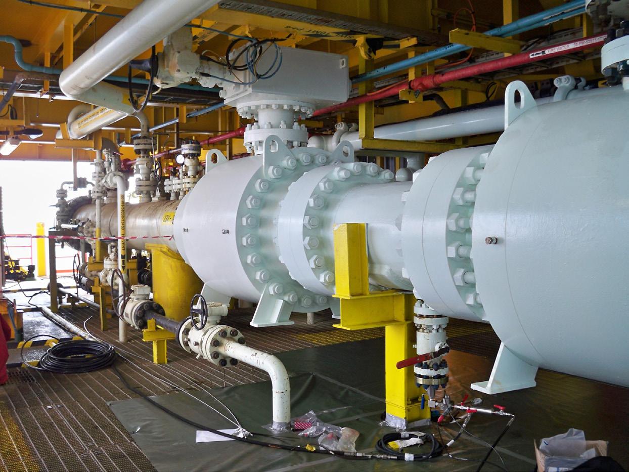
 Figure 4. Typical site installation.


the pipeline a measurable diameter expansion would be created throughout the pipeline if it were free of any blockage. Assuming no expansion is detected then the blockage must be considered to be located between the source and the measuring point. In deep water, this method requires the use of a remotely operated vehicle (ROV), and the approximate location of the deposit needs to be known in advance. Similarly, a major disadvantage is that it cannot be used if there is no direct access to the pipeline, as in the case of buried pipelines.
The radiographic method of detection uses the ability of short wavelength electromagnetic radiation to penetrate various material and is quite accurate when used for short distance inspection. The equipment is typically mounted on an ROV, but the detection ability is affected by the surrounding material of the pipeline, like concrete structures.
Additional areas of application include validation of valve status including speed of operation and validation
of clear passable access which can be useful in providing health data on ESDV operation in order to assure conformance to HSE regulations. Reflectometry has also been successfully used to determine liquid levels in risers or liquid levels in tanks as required.
The simple but effective technology, which is very easy to deploy and rapid to interpret has a whole host of non-oil and gas applications in the water and sewage industry as it is simply providing data on an obstruction within a known volume and distance. Ideal for identifying the infamous ‘fatberg’ which accumulate from congealed fat and reinforced with wet wipes and nappies.
Similarly, there are numerous applications within the renewables industry the system can be usefully applied to check that the pipework and/ or ducts are clear prior to pulling through cables.
Case study – cable pull-through pig site operations
Historically, iNPIPE PRODUCTS have been involved in a number of onshore to offshore cable pull-through pigs and site execution for offshore windfarms. Typically a 12 in. NS HDPE pipeline required a 2 in. messenger wire threading through the 600 m long onshore to offshore pipeline prior to a 5 in. cable pull-through by the client.
The project required mobilisation of site personnel, cable pull-through pig, temporary pig launcher and equipment spread to a site. The pipeline was 12 in. NS in diameter x 600 mm long with numerous bends (size unknown).
Following the mobilisation of the personnel, temporary pig launcher and equipment on schedule, the operation was coordinated in conjunction with a third party on behalf of the end client.
On completion of the ground works and with the pipeline exposed and the temporary launcher/receiver installed complete with a pigging pump fitted, the cable pull through was good to commence. After the pigging of the metal bodied pig, which became lodged due to an unknown crushing of the pipeline, a special dual density foam pig was produced in record time to be on-site and able to run through the pipeline, but also able to negotiate a 45% pipeline reduction. The project, however, was completed successfully and ahead of budget. Acoustek technology now allows for pigging contractors to accurately locate lodged pigs and discuss remedial operations.
References
1. SLOAN, Jr, E.D., ‘Fundamental principles and applications of natural gas hydrates’.
2. WANG, X., SHORT, G., DAWSON, K., LENNOX, B, ‘Acoustic Reflectometry for Gas Pipelines’.
Figure 5. 14 in. x 12 in. temporary pig launcher onsite.
28 World Pipelines / APRIL 2024
Figure 6. 12 in. cable pull-through pig.
Luigi Kassir and Josh Pendleton, Skipper NDT, discuss the drawbacks of manual methods for detecting and locating abandoned pipelines and wells, providing a new solution system that combines several sensors to acquire precise magnetic data.
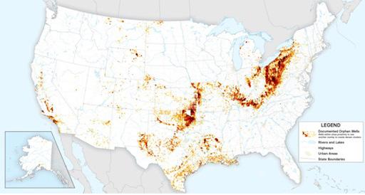
he US is home to over 2 million decommissioned or abandoned oil and gas wells, alongside thousands of miles of decommissioned or abandoned pipelines. Among these assets, some are classified as ‘orphaned’ due to a lack of identifiable owners.
These assets present a significant risk of emitting gases that contribute to safety and environmental hazards.
According to the United States Environmental Protection Agency (EPA), decommissioned, abandoned, and orphaned wells release an estimated
7 - 20 million metric tpy of CO2 equivalent.1
Compounding the issue, these decommissioned or abandoned assets often lack comprehensive records, posing challenges for midstream operators in verifying, mitigating, and avoiding them during other construction activities in affected areas.
The challenge
The primary challenge for operators, in ensuring the safe retirement of decommissioned wells and pipelines, is the verification or establishment of their locations. This challenge is

compounded by the fact that historical records for these assets are frequently incomplete or inaccurate, and the areas they occupy are often vast, remote, and challenging to access.
Traditionally, the detection and locating of abandoned wells have relied on manual methods, such as electromagnetic pipe locators. However, these methods are associated with several drawbacks:
) Field operator safety concerns: many wells are situated in difficultto-access areas, posing potential safety hazards for field operators.
29
) High cost: given the extensive surface areas that need to be covered, deploying field operators to survey the area is timeconsuming and may require significant logistical planning and resources.

) Low efficiency: the manual nature of detection, coupled with the limitations of available tools, results in a lack of guarantee in identifying all targets effectively.
The solution
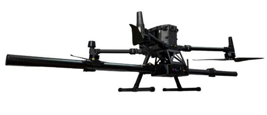
Skipper NDT offers a new technology, the Argos sensor system (Figure 2), that represents a paradigm shift to the efficiency of abandoned well and pipeline detection.
The Argos system combines several sensors to acquire precise magnetic data, free from interferences. Amongst these selected components are:
) Fluxgate magnetometers.
) Real-time global navigation satellite system (GNSS).
) Tactical grade inertial measurement unit (IMU).
) Remote sensors for measuring the distance the between the payload and the ground (for depth of cover assessment).
) A proprietary electronic card for data acquisition, digitisation, and synchronisation.
Among these sensors, fluxgate magnetometers play a crucial role. They can measure all three components of the magnetic field at a sample frequency of 1000 Hz. Compared to scalar magnetometers, fluxgate magnetometers have lighter and more durable sensors, and their sampling frequency is ten to a hundred times higher, making them better suited for UAS constraints.
An important advantage of fluxgate sensors is their ability to capture the 3D components of the magnetic field. Using this feature Skipper NDT has developed a proprietary protocol enabling to compensate any bias of the sensor allowing to increase the native resolution of the sensors 25 times.
By leveraging state-of-the-art hardware and software advancements, Skipper NDT’s Argos sensor stands as a fully automated magnetic-based technology, enabling the precise identification of abandoned wells and pipelines with a remarkable level of confidence and accuracy. The technology effectiveness has been demonstrated through rigorous field testing and validation across numerous abandoned well and pipeline detection missions conducted for leading operators in North America.
The notable advantages of our technology include:
) Remote operation: field operators can conduct scans remotely, eliminating the need to physically navigate challenging or inaccessible terrains, thus ensuring their safety.
) Swift coverage of large areas: through the drone vector, rapid access to complex landscapes, including mountainous regions is possible, enabling coverage of up to 20 acres per day. This capability significantly reduces time and resource expenditure.
) Real-time preliminary processing: the system enables quick preliminary processing of magnetic data directly in the field, facilitating operational responsiveness. Within just 15 minutes
Figure 1. Map showing documented orphaned wells.
Figure 2. Skipper NDT Argos payload on a commercial drone.
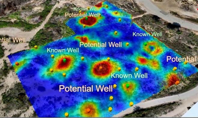
Figure 3. 3D rendering of the inspected site with a photogrammetry layer.
30 World Pipelines / APRIL 2024
Figure 4. 3D rendering of the inspection area with decommissioned pipelines and wells.
THE EXTRA MILE
Qapqa is here to help you make your pipeline construction project to a success.
We not only provide egdecutting automatic welding technology, for fast and reliable welding. We are also a partner you can trust, who is there to support you.
As a family business, we think long term. Dedicated and continuously improving, we always challenge ourselves to go the extra mile.
In everything we do, we maintain the highest standards. Or as we call it: The Qapqa promise.
• Increase productivity
• Increase quality
• Lower repair rates
• High level of support
www.qapqa.com
after a drone flight, analysts can provide field crews with actionable insights.
) Consistent data quality: automated data acquisition and processing ensure reliable and repeatable results, enhancing the overall dependability of the solution. The proprietary data processing algorithms allow to distinguish wells and pipelines magnetic signatures from other sources of background noise.
) Comprehensive geospatial positioning: Skipper NDT’s technology offers enhanced geospatial positioning by integrating additional data layers, such as photogrammetry or
suspected well locations. This feature not only confirms and precisely locates the position of wells or pipelines.
The results
The Skipper NDT technology has undergone extensive field testing and validation through numerous missions focused on detecting abandoned wells and pipelines across 12 distinct sites in California. During the fall of 2023, the system successfully identified over 30 potential wells (Figures 3 and 4). Utilising in-situ preliminary responses during operations, the solution provided real-time guidance for excavation work on the same day.
Skipper NDT’s advanced solution is designed to streamline inspection and excavation tasks, resulting in remarkable efficiency gains. By enabling both tasks to be completed within the same day, Skipper NDT’s technology reduces mitigation response time by over a month.
High voltage Holiday Detector
Detects holidays, pinholes, and other discontinuities using continuous DC
n
i d e s c o m f o r t a b l e a l l - d a y u s e
n O n e w a n d c o v e r s t h e e n t i r e v o l t a g e r a n g e f r o m 0 5 t o 3 0 k V
n U p t o 1 6 h o u r s o f b a t t e r y l i f e p o w e r f u l L i - i o n b a t t e r i e s f i t n e a t l y w i t h i n t h e c o m p a c t w a n d h a n d l e e l i m i n a t i n g t h e n e e d f o r a s e p a r a t e b a t t e r y b o x
n B u i l t - i n C e r t i f i e d Vo l t m e t e r a n d Vo l t a g e C a l c u l a t o r f e a t u r e
n I n d u s t r y s t a n d a r d c o n n e c t o r s a n d a d a p t o r s p r o v i d e c o m p a t i b i l i t y w i t h n e a r l y a l l e x i s t i n g e l e c t r o d e s
Wand-style
Also available with Pulsed DC
Stick-type with Pulsed DC
The comprehensive integrated results delivered by the technology empower clients to:
) Validate existing records with confidence.
) Rectify any misalignments between recorded locations and actual positions in the field.
) Identify previously undiscovered wells, prompting further investigation.
) Strategically plan upcoming inspection and mitigation projects.
) Provide regulators with assurance regarding the accuracy, completeness, and currency of company records.
Looking to the future
Experience a transformative approach to decommissioned/abandoned well and pipeline detection with Skipper NDT’s cutting-edge technology. We’re not merely addressing an urgent environmental concern; we’re revolutionising the landscape of buried asset detection with unparalleled efficiency, safety, and precision.
Gone are the days of manual, labour-intensive methods. The future is automated, streamlined, and dependable with Skipper NDT.
References
1. https://www.edf.org/orphanwellmap
D e Fe l s k o C o r p o r a t i o n l O g d e n s b u r g , N e w Yo r k U S A Te l : + 1 - 3 1 5 - 3 9 3 - 4 4 5 0 l w w w d e f e l s k o c o m
NEW
L i g h t w e i g h t , o n e - p i e c e e r g o n o m i c d e s i g n p r o v
High voltage Holiday Detector
No shoulder bag required!
with Continuous DC
Glen Grundberg, General Manager of Denso North America Inc., Canada (a member of Winn & Coales International Ltd), explains the rigorous training and certification process for liquid epoxy coatings in Canada.
During the late 1990s, the Canadian pipeline market required a new and improved high build, fast curing epoxy that could be applied to work with factory applied Fusion Bond Epoxy (FBE) coatings. The liquid epoxy needed to be capable of being applied in both summer and winter, with significant steel preheat. Moreover, the application process had to be relatively simple and require minimal training. In response to this demand, Denso North America developed Protal 7200TM – as an improvement on our existing Protal 7000TM liquid epoxy coating – to meet the said requirements.
Meeting industry demand
Protal 7200 is a two-part liquid epoxy coating that is VOC-free, 100% solids, and specially designed to complement FBE coated pipes. It is a high-build liquid coating – providing up to 70 mils (1778 microns) in a single coat – that can be applied in either the field or the shop. It cures rapidly, allowing for quick handling and backfill times; can operate at temperatures up to 95°C (203°F); and is our signature liquid coating that is the preferred choice for many of our customers to the present day.
33
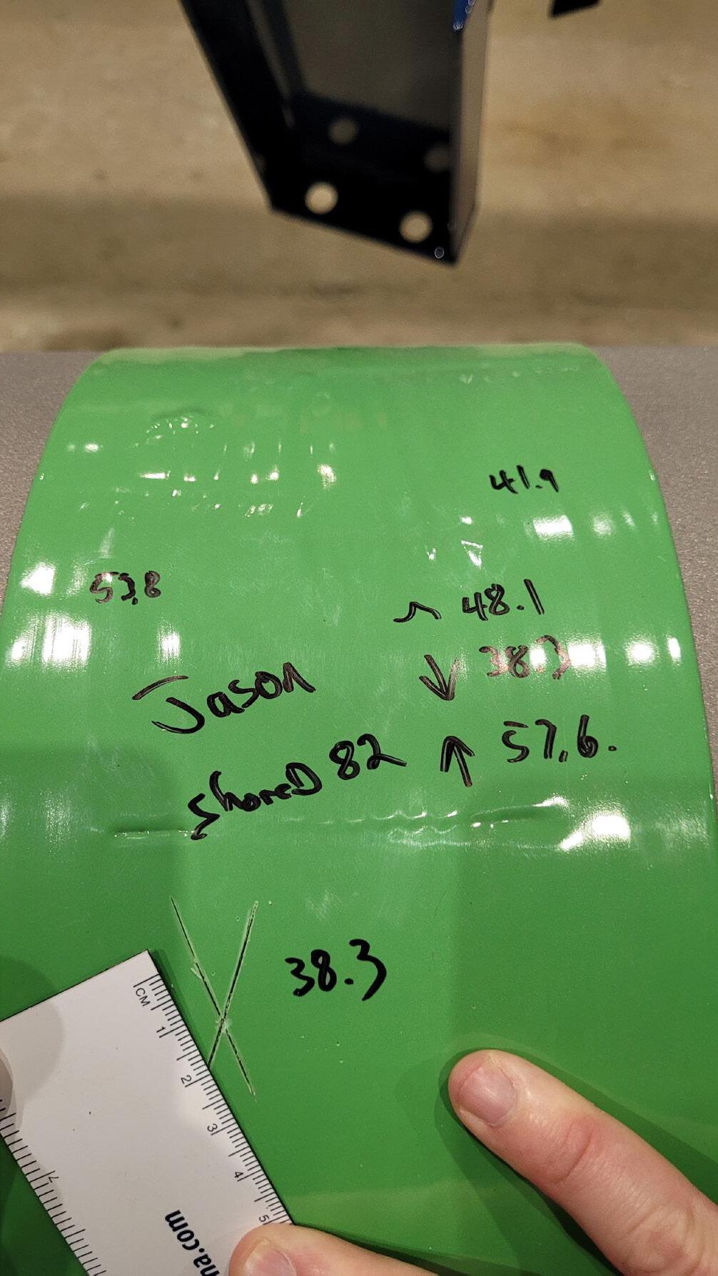
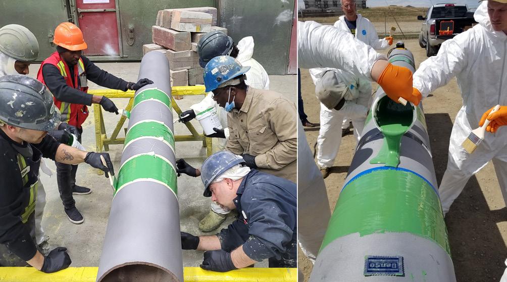
Protal 7200 is designed to be applied using brush, roller or spray application methods. It has always been extremely important to every subsidiary operating within the Winn & Coales International Ltd. (WCI) group of companies that our customers feel confident in applying our range of corrosion prevention systems and we take great pride in training teams to the highest
standard in application methods. With this ethos in mind, and to ensure proper application of our new liquid epoxy coating, a training specification was first created for the brush grade application of Protal 7200. Site training was deemed a crucial element of the specification as many applicators had no prior experience with liquid epoxy application – plus, most of the work was being undertaken on-site.
During the application training of Protal 7200, the first step was defined as ensuring proper surface preparation of the substrate was completed before any other work was started. This process began with surface cleaning, followed by abrasive blasting to produce an angular profile of 2.5 - 5.0 mils, with the abrasive blasting completed to produce a near-white finish (SSPC SP-10, NACE No. 2 or Sa 2 1/2). The substrate temperature range for the application of Protal 7200 was recognised as between 50°F (10°C) - 212°F (100°C). Before proceeding with the coating operation, the substrate temperature had to be seen to be at least 5°F (3°C) above the dew point temperature. This application specification was revised as required, and the training was based on this specification.
The market also demanded a spray grade version of Protal 7200, which could be used in plural component sprayers to mix and atomise 100% solids epoxies. However, using this version of the system required additional training and testing to ensure proper application and performance. To address this, Denso North America Canada developed a spray application approval programme which mandated that a spray applicator intending to administer Protal 7200 complete both theoretical and practical training before undertaking any work using the product. The theoretical training included reviews of product data sheets, material safety data sheets (MSDS) and the spray application specification, while the practical training included surface preparation followed by the application of Protal 7200, as per the spray application specification. The applied panels were then sent to a third-party test lab, where cathodic disbondment and hot soak adhesion testing were performed. Based on the results of these tests, the application company was either deemed to have passed or failed.
A new standard for field-applied coatings
In 2014, the Canadian Standards Association Group (CSA) introduced the CSA Z245.30-14 standard for field-applied external coatings for steel pipeline systems. This standard covered the application of coatings and related activities for steel piping, both in the field and in the shop, and set higher minimum requirements for manufacturers, applicators, and owner groups to attain to. These minimum requirements included performance obligations for coating manufacturers to comply with, as well as applicator training, documentation, and more.
CSA Z245.30-14 covered seven types of coating systems, with liquid epoxies designated as an FC1, FC2 or FC3 system. The CSA standard required coating manufacturers to test their epoxy liquid coatings to specific performance requirements. These test requirements included items such as thickness, shore D hardness, cathodic disbondment, flexibility, impact, adhesion, and gouge resistance. This specification has since been updated and has been revised every four years, with the most recent version published as CSA Z245.30-22.
Figure 1. Protal 7200TM applicator coating inspection.
34 World Pipelines / APRIL 2024
Figure 2. Protal 7200 brush application training.


New open-top wrench design.

Gets the new guy to show up on time.
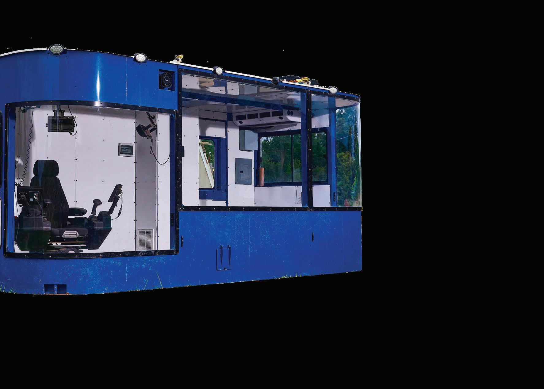
When we built the DD600, we built it based on direct customer feedback. The reason?
So you could have it all. Well, almost all. AmericanAugers.com/DD600

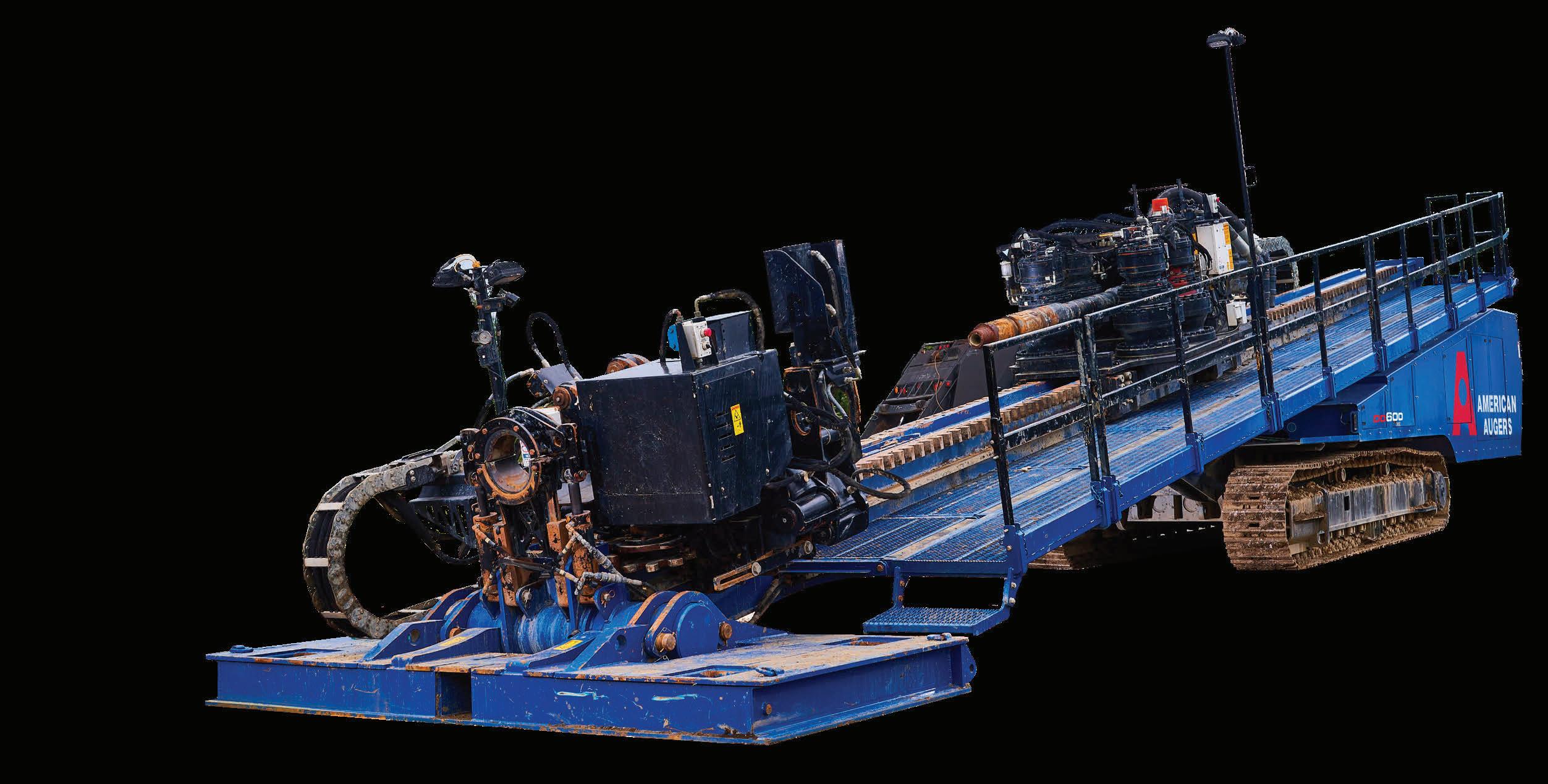
©2024 The Charles Machine Works, Inc.
No DEF required. Faster Setup.
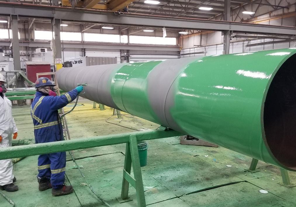
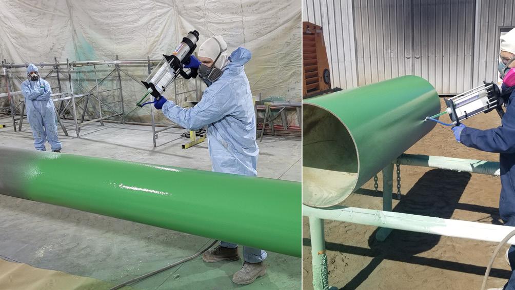
Protal 7200 underwent thorough testing to meet the newly specified requirements and successfully passed all of them. The next step, as per CSA Z245.30-14, was to ensure the proper application of liquid epoxy coatings. This requirement was designated as the Manufacturers Qualified Application Procedure (MQAP) and outlined several requirements that applicators must comply with, including training and certification, necessary tools, surface preparation, preheat methods, substrate temperature, ambient conditions, coating application, curing, recoating, time to backfill, and other essential requirements.
Denso North America Canada therefore met these obligations and created an MQAP which was compliant with the CSA Z245.30-14 standard and is still used to the present day (now in accordance with the revised CSA Z245.30-22 standard). The training for brush, repair and spray cartridge applications outlined in our MQAP once again begins with theoretical training that includes a review of product data sheets, MSDS and the MQAP. After this, the applicator is required to complete the practical application of Protal 7200 according to the MQAP. Once the application is complete, the Protal 7200 undergoes inspection as required by Table 6 in the standard for systems FC1, FC2, and FC3. Upon successful completion of the qualification testing, the application company creates a record of the applicator’s qualification. Additionally, the applicator would also keep a logbook containing information such as the applicator’s name, the application company, project reference, date, type of coating, MQAP, and any other pertinent information. This requirement can be found in CSA Z245.30-22 in section 6.1.3.2.1.
A new wave of trainers
Application training for Protal 7200 required a significant effort from our team due to the sheer number of applicators that required training upon the CSA standard’s release. Denso North America Canada therefore worked with owner groups to develop a programme to train specific approved applicators to assist with training as well. This training was developed as the Denso Application Company Approved Trainer (ACAT) programme and, much like our MQAP, is still implemented today. This programme requires the potential ACAT to have acquired (as a minimum) an AMPP Coating Inspector Programme (CIP) Level 1 Coating Inspection Certificate. The potential ACAT must also be able to generate their own certification cards, build their own database, and conduct a training course supervised by an authorised Denso North America representative. Each ACAT certificate is authorised to be compliant only if the trainer stays with the same application company and is not designed to be transferable when the trainer moves to another organisation.
In adherence to the CSA Z245.30-14 standard, Denso North America Canada also had a requirement to enhance the process of approving spray application companies as well. To improve the proficiency of spray applicators, we developed the Denso North America Canada Qualification Process for Shop and Field Plural Spray Application Companys. This approval requires a higher level of training and applicator competency; a process that involves several steps that must be completed before the spray application approval process can begin.
First, the proposed application company submit a formal request for approval to us (by email) along with a copy of their company’s quality management system (QMS) manual – which must reference compliance to the most recent version of CSA Z245.30. We will then review and determine if the QMS manual is compliant and if an approved application company is required in their local geographical area. If an approved application company is not required in their locale, the proposed application company can still seek approval with the written request of an appropriate owner group or general contractor requesting the company be considered for approval. To maintain our reputation for only approving companies who observe the highest levels of compliance to their QMS and the CSA standard, along with a genuine need for a company with this qualification to operate within their local geographic area, Denso North America Canada will not approve application companies that do not meet the approval criteria.
The proposed application company will then be informed of a site visit to be conducted by a representative of Denso North America Canada. During the visit, the representative will request a resume or work history of the spray applicator(s), including any relevant qualifications such as AMPP CIP certificates. Additionally, the representative will also conduct a protal application company qualification report.
Once the application company is granted permission to proceed, the company must purchase an 800 l kit of Denso Protal 7200 Spray Grade and the Denso North America Canada representative will complete the theoretical training and a review of the Protal 7200 Spray Grade MQAP. Once the theoretical training is complete, our Denso representative has the proposed applicator abrasive blast a pipe with an approved abrasive followed
Figure 3. Protal 7200 plural spray application training.
36 World Pipelines / APRIL 2024
Figure 4. Protal 7200 spray cartridge application training.
We are running out of space...

Our inventory in sales & rental in pipeline equipment is out of this world. We have a huge amount of machines from all the big brands that are ready for worldwide delivery, or even further if you want...
You can build on BAUMA!
BAUMA-PIPELINE.COM Vermiet- und Handels GmbH
by a plural spray application of Protal 7200 on an NPS 6 in. - 10 in. pipe sample with a minimum 4 ft of acceptable coating. This application is completed as required on the Protal 7200 Spray Grade MQAP.
A Denso representative is present for the spray application of the appropriate coating, which is applied in accordance with the Denso Protal 7200 Spray MQAP and all parameters are documented by the proposed application company on a Denso North America underground coating inspection report (or an equivalent coating inspection report, including that of a specific owner group or end user who have submitted the company by request).
Once the pipe has been coated and inspected, the pipe coating sample and underground coating report is shipped to an independent test facility designated by Denso North America Canada. The samples will again undergo cathodic disbondment and hot water adhesion tests which include a range of temperature and duration requirements that each sample must meet. The results of each test will need to satisfy the acceptance criteria of Denso North America Canada before approval is given.
An ash test has also been developed to determine if the applied coating sample has been applied in the correct ratio. We have defined that this test is to be completed on a cured sample of the spray applied Protal 7200 and is given a straight pass or fail result. To be considered for qualified application company approval, each sample must pass this test.
After the laboratory testing is complete, the application company will be notified in writing regarding the status of the tests:


whether the pipe samples have passed the required test criteria and if the application company has been approved. If approved, the company will receive a certificate stating their approval as a Denso approved plural spray application company.
Setting and maintaining the standard
Since the introduction of CSA Z245.30-14, the initial training and approval process for applicators has been significantly improved and the requirements for manufacturer compliance have helped to set a higher level of performance upon liquid epoxy pipeline coatings in general. The additional requirements for training have also ensured that more applicators are operating at a competent level which allows them to correctly apply these high-performance epoxy coatings and achieve the best possible results in terms of performance and project longevity.
Denso North America Canada is committed to following these requirements, with numerous approved application companies and hundreds of approved applicators operating across North America. We’re extremely proud to have earned our position as leaders within the field of corrosion prevention and will continue to maintain and honour the high levels of trust, quality and consistency placed on our products and processes by our customers. Our Protal liquid epoxy coatings have been the tried and trusted choice of pipeline operators for over 35 years, and we continue to work tirelessly to ensure that coatings such as Protal 7200 continues to be the preferred choice for owner groups and contractors worldwide.


Equipped with ultra-slow speed technology that delivers precise thrust control to navigate every foot with confidence, the D550 optimizes cutting action for challenging rock bore conditions. With 100,000 ft lbs (135,581.8 Nm) of torque, you can go from pilot bore to a larger reamer and minimize the number of passes made on a bore. This track-mounted, self-contained maxi rig weighs under 95,000 lbs (with vise removed) while delivering the torque and pullback force typically found in a trailer rig. MORE control. MORE confidence.


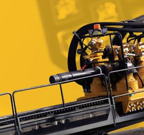


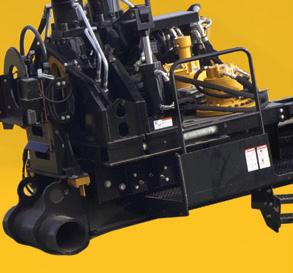
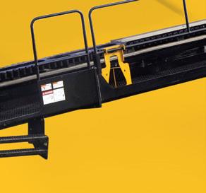






MORE CONTROL, CONFIDENCE. MORE
VERMEER
PUTS YOU IN CONTROL.
THE
D550 HORIZONTAL DIRECTIONAL DRILL
SEE WHY at vermeer.com/D550 Vermeer Corporation reserves the right to make changes in engineering, design and specifications; add improvements; or discontinue manufacturing at any time without notice or obligation. Equipment shown is for illustrative purposes only and may display optional accessories or components specific to their global region. Please contact your local Vermeer dealer for more information on machine specifications. Vermeer and the Vermeer logo are trademarks of Vermeer Manufacturing Company in the U.S. and/or other countries. © 2024 Vermeer Corporation. All Rights Reserved.
The challenges of in-service welding (ISW) operations on a high-pressure, high-flow, large diameter gas pipeline are outlined by Frede Maxwell, Brian Anderson, Paul Gonzales, Darren Sutherland, Bie Cornell and Dave Albertson, WeldFit.
n preparation for the planned expansion of a natural gas pipeline, a major US-based pipeline and terminal company sought a contractor for in-service welding (ISW) operations. The request was a challenging one, not just because the operator was seeking to keep product moving through the system without interruption but also because of the high-flow, high-pressure, and large-diameter characteristics of the pipeline in question. Despite these complexities, WeldFit succeeded in meeting the operator’s needs while remaining on schedule and maintaining high safety standards.
WeldFit was first approached by the company, which owns and operates pipelines and terminals for crude oil and natural gas, in the spring of 2022. The company was preparing to carry out an expansion project that would boost the throughput capacity of one of its natural gas transportation systems to more than 2.5 billion ft3/d, an increase of more than 500 million ft3/d. To support this expansion, the company was seeking a contractor to carry out 13 welding jobs at nine sites along the target pipeline.
More specifically, the pipeline owner/operator was looking for a contractor that could develop ISW procedures specifically for its expansion project, which entailed installations of line stop and hot tap fittings at multiple locations. The job required bespoke, specialised services because of the need to keep natural gas flowing through this complex system at an operating pressure of 1440 psi and flowrate of 42 ft/sec. without any interruptions (Figure 2).
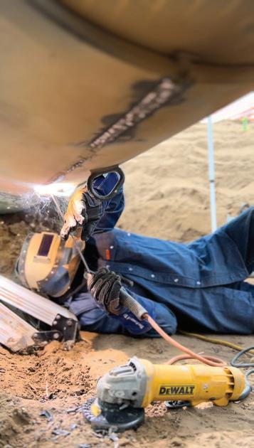
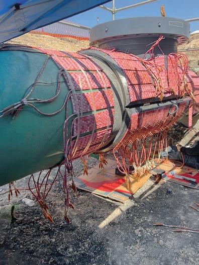
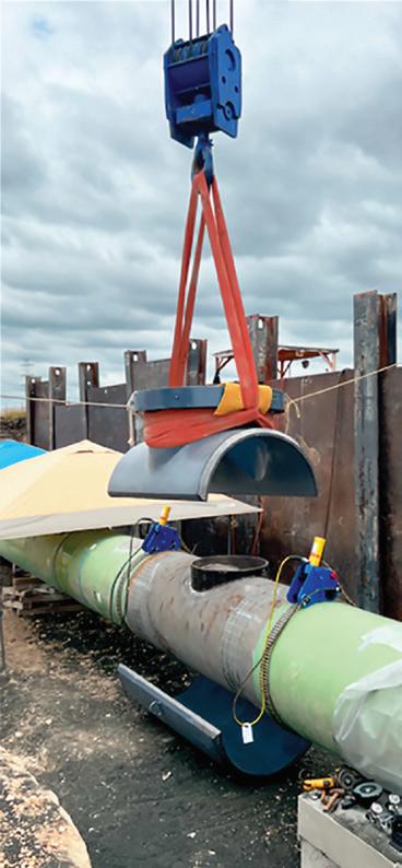
NOT JUST ANOTHER WELD
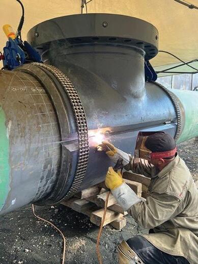
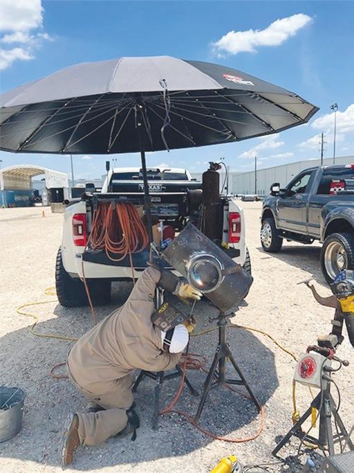
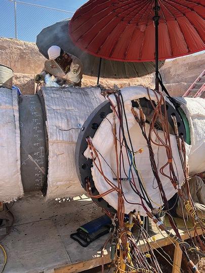
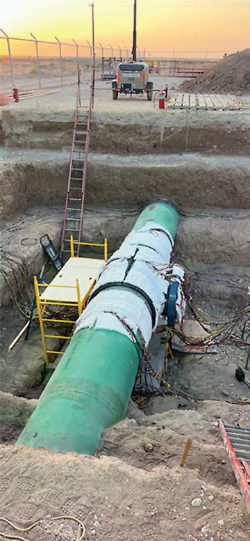

39


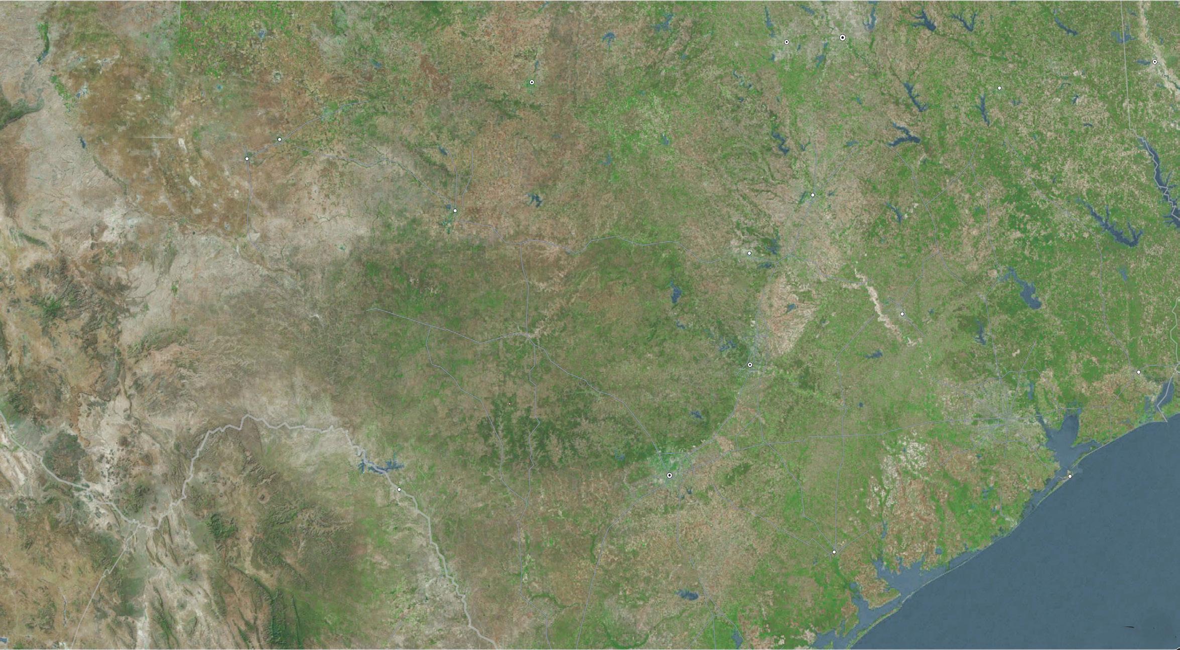
Fitting
Pre-Heating Blanket


Heat loss carried downstream along with flow.
In light of these requirements, WeldFit was a good match, not just as an experienced provider of hot tap and line stop services but also because it offers ISW – a specialised operation that allows fittings to be welded to a live pipeline without any compromise in flow rates or the integrity of the weld – as part of its turnkey line intervention services.
To this end, WeldFit began working with the company to develop ISW procedures for the expansion project which covered a section of buried 42 in. pipeline that is more than 400 miles long. Four of these jobs were to be carried out at four separate locations, each including the installation of two 42 in. x 42 in. x 2.250 in. line stop fittings. Another four jobs were to be carried out at four separate locations, each including the installation of one 42 in. x 36 in. x 2.250 in. hot tap fitting. The final job was to be carried out at a single location and involved the installation of one 42 in. x 30 in. x 2.250 in. hot tap fitting (Figure 1).
The preparations
These jobs had to be planned carefully, as the complexity of the operating environment at each site was certain to make ISW a challenge.
On the one hand, the pipeline company set strict standards for the chemical composition of the materials used. Its gas transportation system was composed of high yield carbon steel pipe, and WeldFit had to manufacture fittings that complied with these standards.
On the other hand, the need to keep gas moving through the pipeline system at 42 ft/sec. made management of heating and temperatures necessary for ISW more complex than usual. (These factors must always be managed carefully during pipeline welding operations in order to ensure the integrity of the weld and prevent delayed hydrogen cracking of the pipe, and management is significantly more difficult than usual during ISW
1 2 3 5 6 7 8 9 4 FITTING 2 42” x 36” x 2.250” hot tap split tee fitting ( x1 ) 1440 psi / 42 fps / x70 carrier pipe FITTING 3 42” x 30” x 2.250” hot tap split tee fitting ( x1 ) 1440 psi / 42 fps / x70 carrier pipe FITTINGS 4 & 5 42” x 42” x 2.250” line stop split tee fitting ( x2 ) 1440 psi / 42 fps / x70 carrier pipe FITTINGS 8 & 9 42” x 42” x 2.250” line stop split tee fitting ( x2 ) 1440 psi / 42 fps / x70 carrier pipe FITTINGS 1 0 & 1 1 42” x 42” x 2.250” line stop split tee fitting ( x2 ) 1440 psi / 42 fps / x70 carrier pipe FITTING 12 42” x 36” x 2.250” hot tap split tee fitting ( x1 ) 1440 psi / 42 fps / x70 carrier pipe FITTING 13 42” x 36” x 2.250” hot tap split tee fitting ( x1 ) 1440 psi / 42 fps / x70 carrier pipe FITTING 1 42” x 36” x 2.250” hot tap split tee fitting ( x1 ) 1440 psi / 42 fps / x70 carrier pipe TYPICAL Process Per Fitting 1. Fitting delivery 2. Fit-up, prep and install 3. Controlled electrical resistance preheat 4. In-service ( live line ) welding - Weld long seams - Weld downstream fillet - Weld upstream fillet 5. Preheat removal 6. Non-destructive examination FITTINGS 6 & 7 42” x 42” x 2.250” line stop split tee fitting ( x2 ) 1440 psi / 42 fps / x70 carrier pipe
Figure 2. Controlled electrical resistance heating blankets were used for preheating the fittings and pipeline to slow the high cooling rate caused by the normal operational flow rate of 42 ft/sec.
40 World Pipelines / APRIL 2024
Figure 1. High pressure, high-flow large diameter gas pipeline, in-service welding job with nine sites and 13 fittings spans 400 miles –projects completed while remaining online.
MITIGATE AC INTERFERENCE AND OPTIMIZE YOUR CP SYSTEM
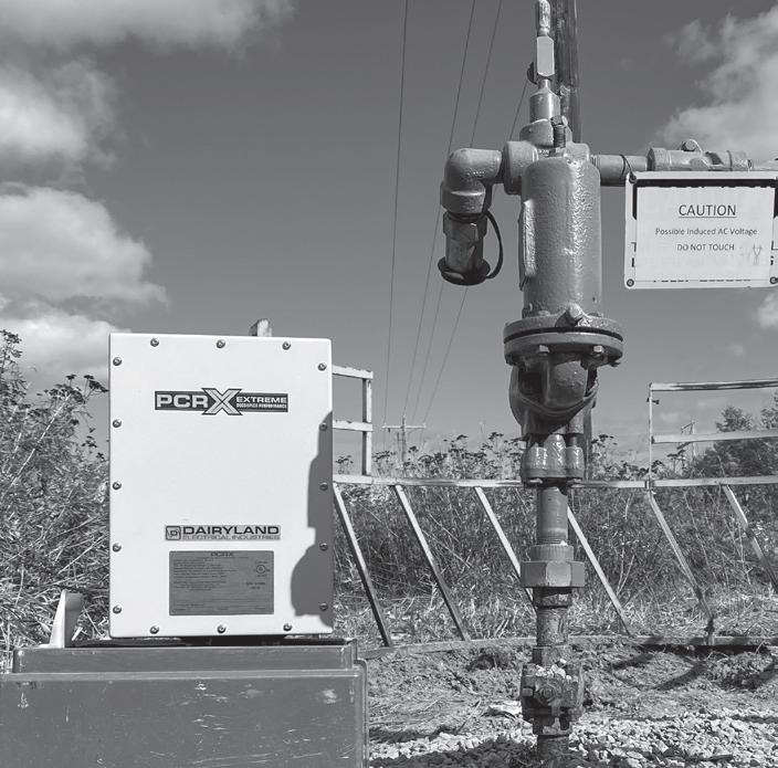
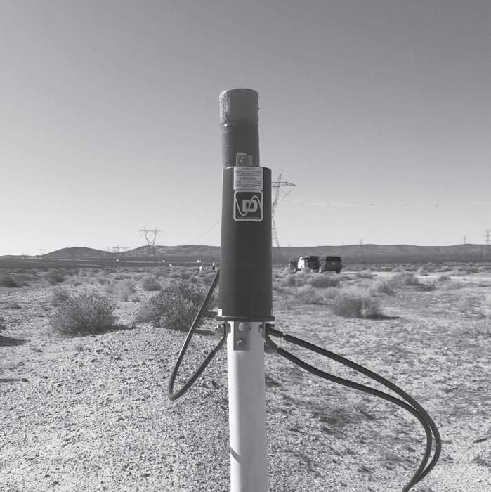
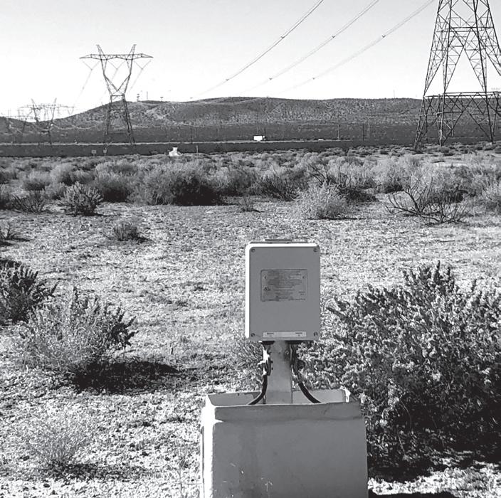
When your pipeline shares a right of way with high-voltage power lines, the electromagnetic field on the power lines can induce unwanted vol tage onto the pipeline, creating a safety hazard for personnel and contributi ng to AC corrosion problems. Dairyland decouplers provide an effective grounding path that mitigates induced AC, while simultaneously maintaining DC isolation to optimize your CP system. With a Dairyland decoupler, your CP system will continue to work efficiently, and the pipeline and personnel will be safe from AC interference.


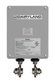

Learn more about the world’s leading manufacturer of solid-state decoupling products at Dairyland.com
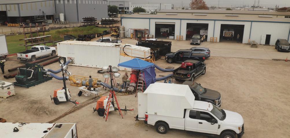
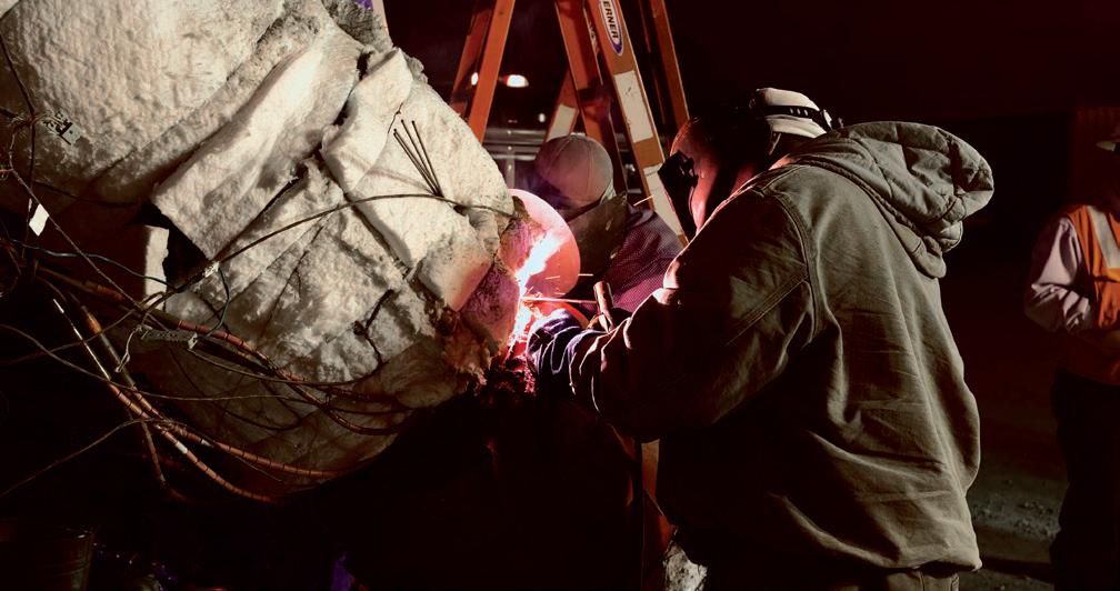
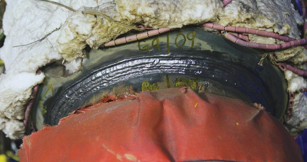
operations, when product flows affect both heat dispersion and rates of cooling).
WeldFit addressed the first challenge by special-ordering the fitting material for manufacturing at its WeldFit - Houston facility. This was necessary to meet the client’s chemistry requirements but it also slightly increased the lead time before welding could begin.
Next, WeldFit addressed the second challenge by simulating working conditions ahead of time so that it could optimise heating and temperature management. To achieve this end, it first modelled the welding conditions at all nine sites using finite element analysis (FEA) software. Subsequently, it constructed a test loop – a physical model of the pipeline system – to analyse temperature fluctuations and heat dispersion under conditions that closely resembled ISW operations.
The test loop was fabricated with a 10 000 gal. water tank, a 7000 gal./min. water pump, an inline flowmeter to verify flowrates, and a 16 in. header with a 2.25 in. thick sleeve that
included a 45° bend (Figure 3). During simulations, water was circulated through the test loop in order to replicate a gas pipeline system with operating conditions of 1440 psi and 42 ft/sec. (Weldfit actually conducted three sets of simulations in order to develop welding procedures for the two different types of pipe – namely, X70 carrier pipe and X65 split-tee fitting – used in a branch connection as well as the main trunk line).
The results secured from the test loop showed that WeldFit’s proposed ISW procedures were both acceptable to the client and in line with data collected during pre-weld analysis. As such, WeldFit and the pipeline company were able to reach agreement on the project and begin execution planning (Figures 4 and 5).
The proceedings
To execute the project, WeldFit assembled a specialised crew of highly qualified welders. That is, it turned to its in-house ISW staff, whose members have as much as 18 years in live line welding experience, as well as an additional average of 10 years of general experience in welding in the oil and gas industry.
The team faced a number of challenges – and not just because of the large-diameter, high-volume, and high-pressure characteristics of the pipeline. It also had to begin the operation during the summer months, at a time when the weather at this project location was hot enough to impose extra burdens on personnel while also complicating the task of heating and temperature management. Additionally, it was tasked with installing fittings on a spiral-welded pipeline made of high yield strength material that required 100% X-ray scanning of weld seams prior to grinding flat for clearance.
All of these factors increased the difficulty of completing the welds in line with the client’s specifications – that is, in a manner that would allow gas to continue flowing through the pipeline without reductions in pressure or flow rates, even though the continuous movement of product through the system would inevitably cause heat to disperse and temperatures to fluctuate in ways that could threaten the integrity of the weld and/or cause other issues to come into play.
WeldFit was able to resolve these challenges. Based on the data collected during the modelling process, it opted to provide 24 hour coverage so that pipes and fittings could be pre-heated to approximately 200°F and 350°F, respectively, and then maintained at constant temperatures in order to control the speed of the weld cooling. This level of control was necessary to mitigate high heat-affected zone (HAZ) hardness, which makes steel pipe more susceptible to delayed hydrogen cracking.
The professionals
To enable this 24 hour coverage and also keep the project on schedule, WeldFit assigned ISW team members to multiple types of crews – specifically, set-up crews, welding crews, and inspection crews – that rotated between job sites.
The set-up crews were always the first to arrive at each site, and they were tasked with grinding pipe, installing fittings, clamping fittings in place, and tack welding the fitting to hold them in place temporarily.
Figure 3. WeldFit’s test loop enables complete verification prior to project execution.
Figure 4. Heating blankets used to preheat the fitting and pipeline to proper temperatures during simulation at the test loop.
42 World Pipelines / APRIL 2024
Figure 5. Circumferential weld made at test loop during simulated conditions.

Expect A Higher Standard
Once they met these milestones, they then proceeded to the next site to begin another round of preparatory work – and to make way for the welding crews.
The welding crews, in turn, built on the preliminary work carried out by the set-up crews. They were able to start work quickly, moving straight away to pre-heat the materials to the required temperatures before proceeding to the permanent welds.
Once they completed their tasks, they then proceeded to the next site and made way for the inspection crews. The inspectors, in turn, examined and assessed the work of the other two crews and made arrangements for the relevant crews to come back for corrective action, if necessary.
This rotating arrangement allowed WeldFit to optimise the efficiency of its ISW staff. It facilitated the provision of 24 hour coverage – which provided tangible benefits, such as improved control over heating and temperature conditions – while also allowing for quick movement between the nine job sites along more than 400 miles of pipeline over a period of about three months.
The results
Work on the project was completed in autumn 2023. At that time, the client determined that WeldFit had executed the work to its satisfaction – that the appropriate welding procedures had been developed and implemented on schedule, without disruption in gas flows through the pipeline or compromises in weld quality and the integrity of the pipeline system.
“We attribute these successes in large part to sophisticated modelling procedures and skilled personnel,” said Frede Maxwell, In-Service Welding Manager at WeldFit. “Virtual and physical modelling allowed WeldFit to plan ahead, making the necessary arrangements to manage heating and temperature conditions, even at a time when hot summer weather made efforts to ensure appropriate rates of weld cooling and the avoidance of weld degradation as a result of potential delayed hydrogen cracking even more complex than usual.”
“Meanwhile,” continued Maxwell, “WeldFit’s highly capable and experienced ISW crew members were able to implement a rotating schedule that allowed them to optimise resources, stick to a prescribed timeline, and manage heating and temperature conditions as needed to keep product moving through this high-capacity pipeline without reductions in pressure or rate.”
Brian Anderson, CEO and President of WeldFit, added that the factors that made this particular project a success can be replicated – and revised or scaled as necessary to accommodate pipelines operating under different parameters of size, pressure and flow rates.
“Access to appropriate modelling methods helped WeldFit develop welding procedures for this project that took the heat dispersion and temperature fluctuations inherent in ISW operations into account,” said Anderson. “At the same time, the deployment of crews with ISW-specific experience and qualifications ensured that we had the resources needed to execute this complex work plan and meet our customer’s expectations.”

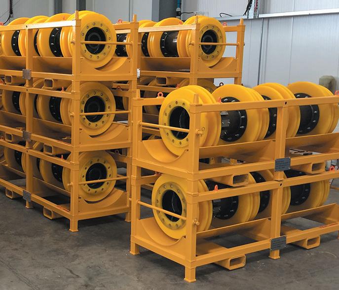
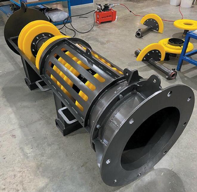

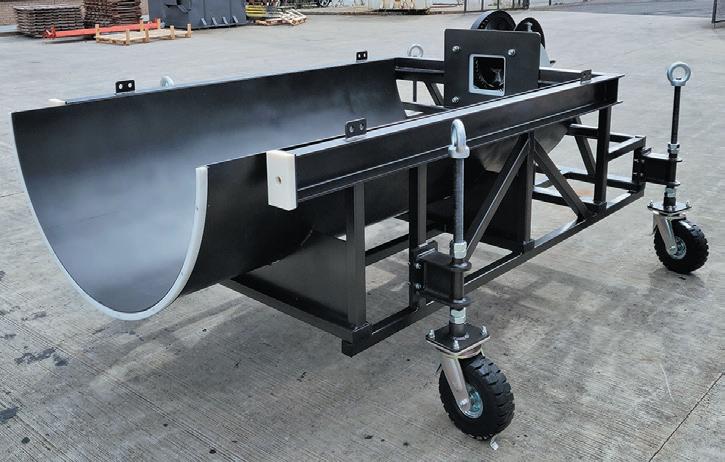
PIG HANDLING EQUIPMENT Propipe manufactures pig handling equipment for a wide variety of applications, from loading of precommissioning pigs, as well as routine maintenance operations, to receiving cassettes, removal tools and storage trays. All equipment is manufactured to suit project specific requirements. Propipe Limited - www.piggingsmarter.com For Global Sales For North American Sales Tel: +44 1429 872927 Tel: +1 902 417 5075 Email: groupsales@propipe.co.uk Email: sales@propipenorthamerica.com
Jay Warner, Dairyland Electrical Industries, USA, Jerzy Sibila and Jerzy Mossakowski, CORRSTOP, Poland, explain how AC mitigation is a proven technique to solve AC interference problems on pipelines, referring specifically to the use of DC decouplers.
making a

herever high voltage AC (HVAC) power lines or AC railway lines are in proximity with steel pipelines, there are risks and challenges associated with AC interference on the pipeline1. However, remediation efforts are often neglected for the sake of short-term cost savings. In the long run, ignoring AC interference can result in devastating results associated with accelerated pipeline corrosion or rupture and/or personnel safety hazards.
At a minimum, pipeline operators need to understand the degree of AC interference on their pipelines in terms of AC voltage potentials and AC current density and
have mitigation and monitoring plans in place where these measures exceed industry criteria.
For decades, as pipeline operators have been made more aware of the potential hazards of AC interference, AC mitigation systems have become increasingly common worldwide. As critical components of AC mitigation systems, DC decouplers allow cathodic protection (CP) systems to work effectively in concert with AC mitigation systems by isolating CP systems from earthing systems while maintaining a low impedance path to earth for AC and lightning.
Introduction to AC mitigation
AC interference
Growing global electrical power demand has brought about a steady increase in co-located HVAC power lines and buried pipelines within utility corridors, especially in regions with higher population density. With this has come growing challenges related to the influence of AC power on the pipelines, commonly referred to as AC interference.
The most common form of AC interference on buried pipelines is caused by the magnetic field associated with current flow on the nearby power line.
45
This magnetic field induces a steady state AC voltage and current onto the pipeline, the degree of which is affected by many factors, including powerline load current, separation distance of
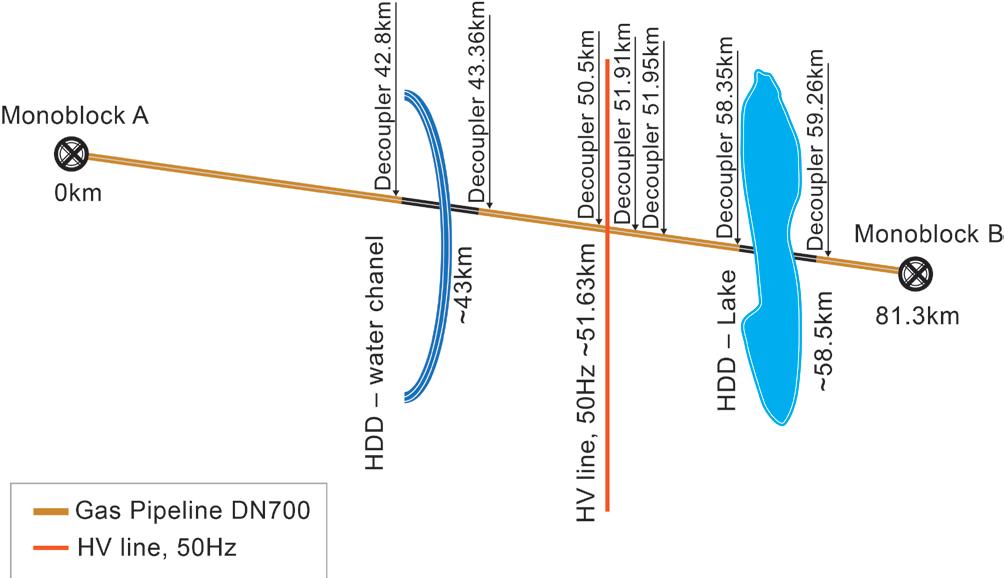
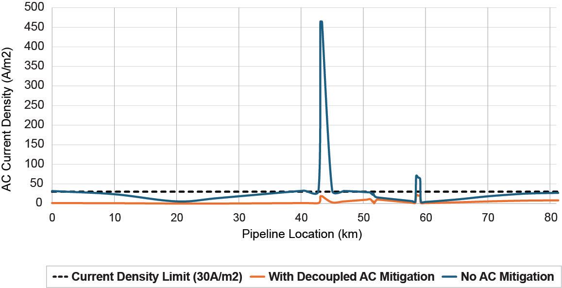

each phase from the pipeline, phase transpositions, changes in pipeline distance or orientation, soil resistivity, and coating quality.
Induced AC voltage on pipelines is highly undesirable because it can 1) create hazardous touch and step voltage conditions for persons who come into contact with the pipeline and related appurtenances, and 2) cause accelerated corrosion at small coating defects due to AC current discharging from the exposed metal to the surrounding soil: a phenomenon referred to as AC corrosion.
Related to human health concerns, industry standards such as NACE SP0177 and EN 50443 set limits for AC touch voltage during normal operating conditions. The specified limits for human health range from 15 V in NACE SP0177 to 60 V in EN 50443. These levels are steady-state values, and under fault conditions the induced voltage will be much higher. EN 50443 also provides AC touch limits under fault conditions.
Even when AC pipeline potentials are well within these limits set for human health, AC corrosion can easily occur and threaten the integrity of the pipeline. An unwanted consequence of new, high resistance coatings, AC induced current exchange between the pipeline and soil at small coating defects can achieve very high current densities – the amount of current flow per square unit of area. Most standards recommend a maximum AC current density of 30 A/m2 with higher limits allowed when cathodic protection current density is less than 1 A/m². The risks of AC corrosion should always be considered, as it may require further reduction of the pipeline AC voltages from the levels adequate for human health protection. However, in general, only for areas with low soil resistivity (<300 Ω-m) are there typically concerns with AC corrosion.2
In addition to steady state induced interference that occurs during normal operating conditions, AC faults on the powerline, which may occur with some form of insulation breakdown, result in a temporary, high amplitude induced voltage and current flow on the pipeline. This occurs in the same manner as the steady-state effect, but at greatly elevated levels that can create dangerous touch and step voltage for workers, and possible insulation breakdown and arcing on pipeline systems.
AC mitigation systems
AC mitigation systems are commonly applied on pipelines to dissipate unwanted voltage along the pipeline resulting from induced AC and AC faults. The general technique employed is to connect the pipeline at appropriate locations to a suitably low impedance earthing system in order to collapse the voltage to a safe value. The earthing system is commonly continuous bare zinc ribbon or copper wire run in parallel along a pipeline segment or point wells for more localised point mitigation.
The design process typically begins with software modelling by specialised consultants, incorporating various factors such as soil resistivity, separation distance, voltage and current to arrive at a voltage map at all points along the pipeline. Then, by applying low impedance earthing points at various locations along the affected area, the AC effects under steady-state and fault conditions can be modelled, and the earthing system design can be optimised to address worker safety, coating stress voltage, and AC corrosion issues. Depending on the many site variables, the spacing of earthing connections may vary between a few hundred metres to several kilometres.
Figure 1. AC mitigation installation on a gas pipeline near an HVAC crossing.
Figure 2. Modelled results of AC current density on a 81 km, DN700, 3LPE coated pipeline with and without AC mitigation.
46 World Pipelines / APRIL 2024
Figure 3. An AC mitigation system and cathodic protection with DC isolation using decouplers.
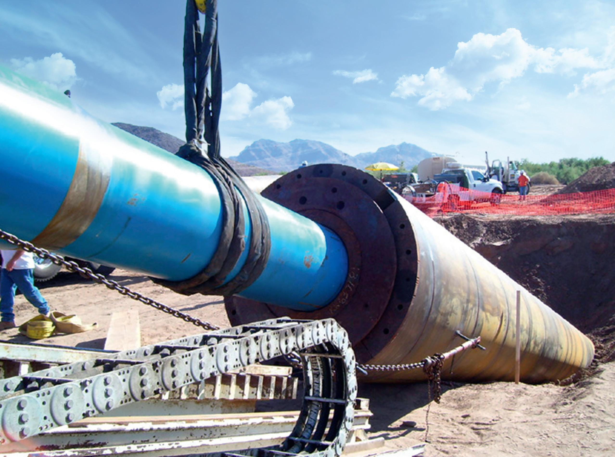
A DRIVING FORCE FOR YOUR PIPELINE PROJECTS? GRUNDORAM – HDD ASSIST The GRUNDORAM ramming machines provide thrust forces up to 40.000 Nm for installing casing or product pipes up to 4.000 mm diameter in any kind of soil. Plus the powerful rammers can fix problems occuring during complex HDD pipeline installa-tion projects applying HDD Assist & Rescue methods. NEED SUPPORT WITH YOUR PROJECT? We can provide equipment, consultancy and hands-on training! Contact us for details: T +49 2723 808-0 M info@tracto.com TRACTO.COM/GRUNDORAM
NEED
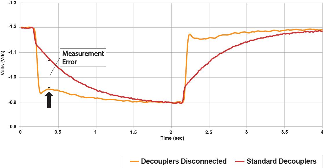

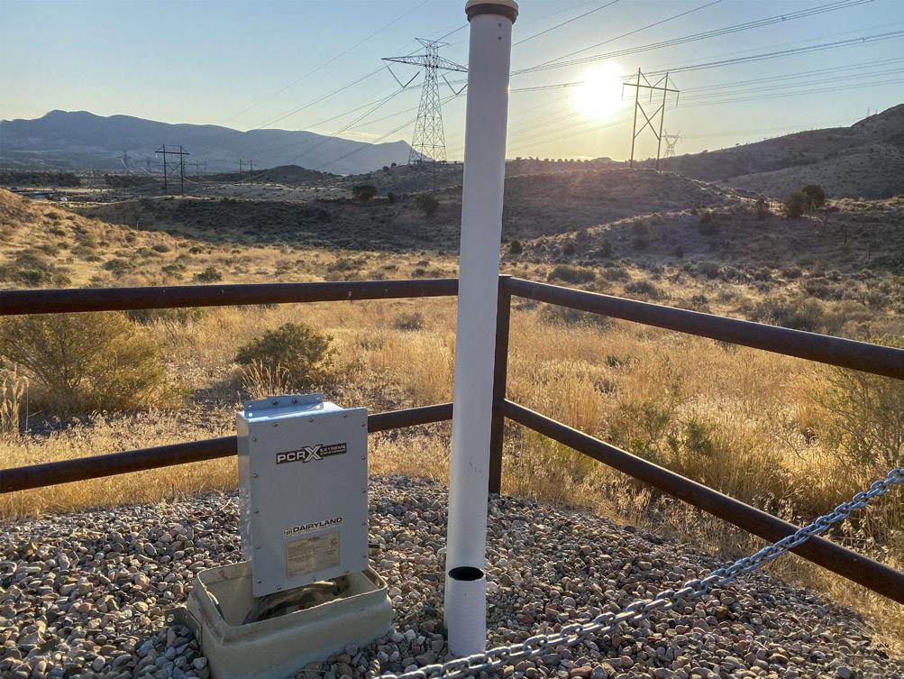
Shown in Figure 1 is an example of an AC mitigation system installed on a 3LPE coated gas pipeline in eastern Europe. The mitigation system consists of seven bonds to an earthing system through Dairyland decouplers. Figure 2 shows the modelled AC current densities with and without mitigation. In this application, though the unmitigated AC pipeline potentials were only about 5 V at maximum current loading, because sections of the pipeline were laid under bodies of water where the soil resistivity is very low (~2 Ω-m), the resulting AC current densities at these
sections were predicted to be as high as 450 A/m2, far above the recommended limit of 30 A/m2. Installation of the decoupled mitigation system significantly reduced the measured AC current density at these locations to below 65 A/m2 with the majority of the pipeline below 30 A/m2
AC mitigation and cathodic protection
The impact of AC mitigation on CP potentials AC mitigation systems have proven to be highly effective at maintaining safe pipeline AC voltage potentials and minimising AC corrosion.3 However, the mitigation earthing system that allows AC to drain off the pipeline also provides a low impedance path for CP current to flow between the anode bed and the rectifier negative terminal. The earthing system, now electrically bonded to the pipeline, introduces significant additional material surface area for the CP system to protect. As a result, the rectifier often cannot support the increased current load and CP potentials can become compromised, leaving the structure inadequately protected.
When faced with insufficient CP potentials due to the required earthing bonds, CP designers might be inclined to add more rectifiers and anode beds and tolerate high CP current demand. However, this is likely a prohibitively expensive option and may ultimately not provide sufficient corrosion protection. In addition, there is the risk of driving the DC voltage on the pipeline to higher than recommended levels that may impact coating quality.
DC decouplers
A practical and widely accepted solution is to install Dairyland DC decoupling devices in series with the bonding connections between the cathodically-protected structure and the earthing systems as shown in Figure 3. Dairyland decouplers are designed to block CP current while allowing steady state AC, AC faults and lightning to pass freely. This prevents CP current from passing through the earthing systems and so dramatically reduces the amount of CP current required to protect the pipeline.
Dairyland decouplers use high power solid-state electronic switching components to maintain DC isolation between structures. Under normal conditions, the circuit remains open, maintaining DC isolation between the structures. When the differential voltage across the terminals exceeds a prescribed voltage threshold, which would occur during a fault or lightning event, the circuit closes virtually instantaneously and electrically bonds the structures. Immediately following the over-voltage event, the device then automatically switches back to the open state to maintain DC isolation.
Most global standards pertaining to cathodic protection and AC mitigation, i.e., NACE SP0177, EN 15280, ISO 18086, ISO 15589-1, and EN 50443 recommend the use of DC decouplers as part of AC mitigation systems.
Be mindful of waveforms during interrupted surveys
During interrupted surveys such as close interval potential surveys (CIPS), the interrupted response can vary greatly depending on the number of traditional decouplers present, as well as other
Figure 4. An example of the potential effect of traditional decouplers on instant-off response. In this example, the pipeline segment is 33 miles long with eight decouplers installed for AC Mitigation.
Figure 5. The instant-off response on the pipeline from Figure 4 using PCRX vs. traditional decouplers.
48 World Pipelines / APRIL 2024
Figure 6. A Dairyland PCRX decoupler installed as part of an AC mitigation system.
parameters such as soil resistivity and pipeline coating. If not accounted for, certain combinations of these parameters can lead to instant-off readings that are more electro-negative than the true polarised potential as shown in Figure 4.
Therefore, before recording instant-off measurements, CP technicians should evaluate the interrupted response to determine if decoupler capacitance could be affecting the readings and, if necessary, take appropriate steps to mitigate the effect.
One common solution is to temporarily disconnect the decouplers from the pipeline during the survey. This is effective in eliminating the transient current flow from the capacitor during the OFF cycle and the resulting IR drop. This can be accomplished by physically disconnecting leads or by the use of decoupler isolation switches. However, one should be aware of the impact this approach may have on AC potentials and current density while the decouplers are disconnected.
Another solution is to employ decouplers having active capacitance compensation, such as the Dairyland PCRX.4 The PCRX overcomes the slow interrupted response associated with decoupler capacitance while providing the same benefits of traditional solid-state decouplers. An example of the instant-off response using this technology compared to traditional decouplers is shown in Figure 5. The decoupler remains in the circuit at all times during interrupted measurements to provide continuous protection from AC interference and lightning. In addition to the safety and protection benefits, long term cost savings are realised using the PCRX by not having to disconnect/ reconnect the decouplers for every survey.
Conclusion
Pipeline AC interference is a growing problem wherever high voltage AC power lines are located near buried pipelines. Not only can induced AC voltage cause unsafe touch and step voltages for personnel who come into contact with the pipeline, it can also increase the likelihood for AC corrosion which can quickly perforate pipe walls where the bare pipe surface at coating defects comes into contact with low resistance soil. AC mitigation is a widely accepted and proven technique to solve such AC interference problems on pipelines.
DC decouplers, a critical component of AC mitigation systems, dramatically improve the performance of CP systems by preventing CP current from flowing through, and thus protecting, the earthing system. It is important to be aware of the effect of decoupler capacitance on
measured instant-off potentials. To ensure accurate and efficient CIPS surveys, waveforms should be reviewed and, where needed, decouplers should either be temporarily disconnected during the survey or decouplers with active capacitance compensation, such as the Dairyland PCRX, should be used.
References
1. GUMMOW, R.A., WAKELIN, R.G. , and SEGALL, S.M., ‘AC Corrosion – A New Challenge to Pipeline Integrity’, CORROSION/98, paper no. 566. Houston, TX: NACE, 1998.
2. NACE SP21424 (latest revision), ‘Alternating Current Corrosion on Cathodically Protected Pipelines: Risk Assessment, Mitigation and Monitoring’ (Houston, TX: NACE).
3. BAHGAT, H., SEGALL, S., SHEN, K., HEBB, D., GUDINO, E., and JIANG, S. ‘Case Study –Sharing an AC Mitigation System’, AMPP Paper No. 17786. San Antonio, TX, 2022.
4. WARNER, J., HILGART, R., ‘A New Solution for Efficient, Accurate, and Safe Interrupted Surveys’, Pipeline Technology Conference, Berlin, 2022.

Industrial pipelines, which are under constant threat from corrosion, are critical pieces of infrastructure that must be suitably protected using cathodic protection (CP) systems otherwise serious and permanent structural damage can occur. However, engineers and asset managers regularly face challenges in monitoring CP systems in pipeline applications because of challenges associated with cost and accessibility. Here David Celine, Managing Director of remote monitoring specialist Omniflex, explains why, in a plant environment, engineers and plant managers should opt for short range wireless technology, such as LoRa, to monitor ongoing CP system performance and pipeline corrosion levels.
CP systems come in two main forms: galvanic CP and impressed current CP (ICCP). Galvanic CP is a passive technique

where a buried or submerged steel structure is connected to a metal alloy with a more negative electrode potential than it, such as magnesium, aluminium or zinc. This guarantees that the metal structure is always the cathode of the electrochemical cell, and the metal alloy becomes a sacrificial anode that is consumed by corrosion, rather than damaging the structure. These sacrificial anodes can then be easily replaced when they have fully corroded, ensuring ongoing protection.
In ICCP systems, a current is externally injected into the structure to ensure that the structure remains cathodic with respect to its environment. This is done by using a series of anodes that are connected to a DC power source by way of a transformer/rectifier (T/R), which is normally powered by the mains AC grid with a solar power backup supply.
50

The ranges of CP monitoring
David Celine, Managing Director, Omniflex, explains why engineers should opt for short range wireless technology to monitor ongoing CP system performance and pipeline corrosion levels.
51
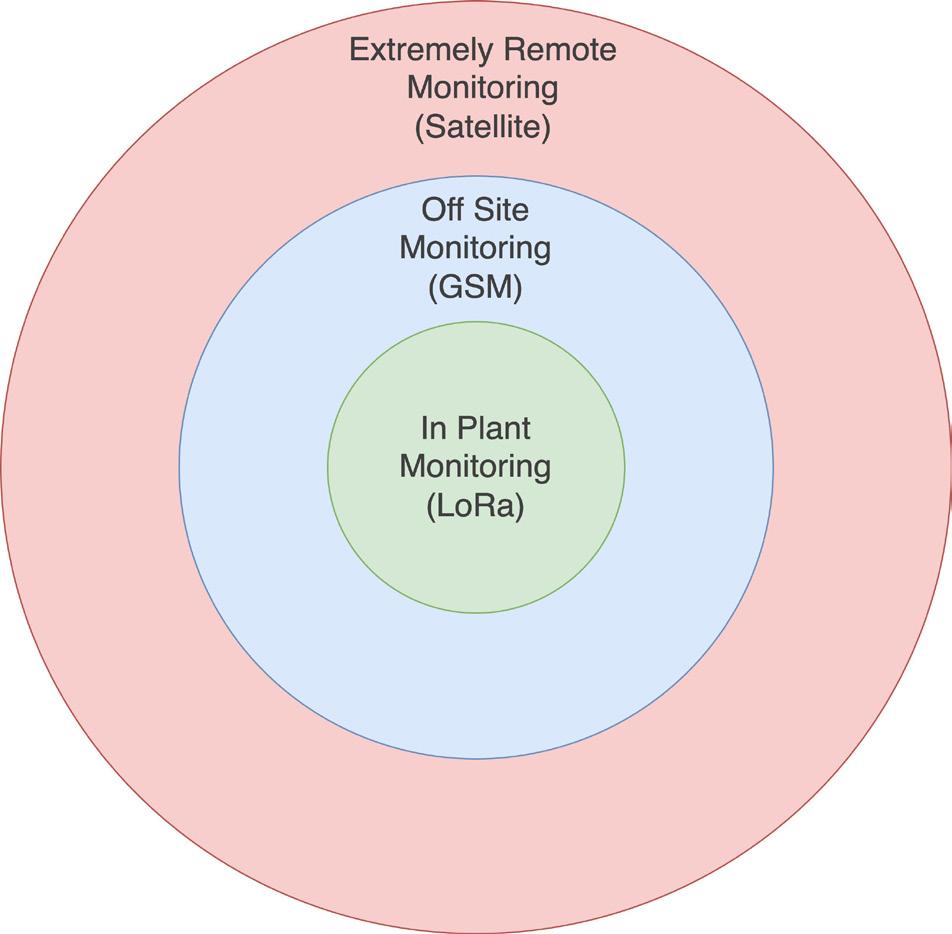
Traditionally, galvanic CP systems haven’t been able to offer significant protection for larger structures, like industrial pipelines, bridges or wharves, so ICCP is normally the preferred systemtype for these applications.
Pipeline CP
When we think of pipeline infrastructure, we generally think of water, oil and gas pipelines stretching over hundreds of kilometres, often across remote and difficult-to-reach environments. These are generally protected using ICCP systems that are powered by T/Rs installed up to tens of kilometres apart along the pipeline. To test ongoing protection in these situations, ‘instant-off’ tests are performed to measure pipe potential using buried reference electrodes connected to test points installed in test posts that sit alongside the pipeline every kilometre or so.
Due to the cost of travelling the length of the pipeline to manually take measurements at each test post, there is a drive toward remote monitoring of pipeline CP test points.
Traditionally, in these situations, there has been no choice but to use publicly available wireless infrastructure, such as mobile phone networks to monitor pipeline CP systems that are in place to safeguard against corrosion. This approach often had prohibitive capital and operating costs associated with it, which is why pipeline CP systems were left unmonitored and asset managers relied on routine manual inspections to check system status.
Having no mobile network coverage available for remote monitoring of pipeline CP systems has also traditionally been a major problem for industrial pipelines in extreme remote locations. However, recent advancements in IoT satellite technology have changed the landscape of remote-area pipeline CP monitoring by providing a low-cost solution that facilitates 24/7 remote monitoring. For example, Omniflex’s Teleterm SW1 module is an IoT-focused satellite-based remote monitoring module for the global CP market and this is particularly beneficial for these remote area pipelines.
However, these remote area pipelines are not the only example of pipeline CP systems where monitoring can be optimised. In-plant environments also face their own unique challenges with pipeline CP monitoring. Whether it be a pump station, processing plant or a refinery, plant environments globally have extensive pipeline networks that face the threat of corrosion without effective CP in place.
Long range battery-powered wireless
Depending on their size and purpose, plant environments can vary massively in the number of pipeline test points on a site. I have encountered small pump stations with only a handful of test posts to monitor, and large refineries with hundreds of on-site pipeline test points to monitor.
Clearly, gathering ongoing system data from these test posts is a must if engineers and asset managers are to know for certain that pipelines are protected against corrosion. However, for sites that tend to be up to 10 km2 in size, it makes little sense to opt for GSM or satellite-based monitoring technology in the same way as we discussed previously for remote-area pipeline CP monitoring because of the otherwise-avoidable operating costs that come with it.
Monitoring a test station wirelessly using GSM currently costs at best about US$1 per month per test station, which might not sound like a lot, but, for plants with upwards of 100 wireless test stations to monitor, this can cost thousands of dollars per year.
For example, the Sasol chemical plant and refinery in South Africa has about 400 pipeline test posts across its sites and would have to spend nearly US$5000 per year to monitor them all using GSM.
Clearly, when monitoring test points over a large, dispersed area, GSM is a cost-effective solution as you would save money by paying for this instead of sending a technician to physically visit all sites and manually collect system data. However, GSM is not the most cost effective solution for in-plant environments.
In these situations, battery-powered wireless solutions with a battery life of years are preferable. However, these have been previously limited in capabilities because of the short operating range of available technologies such as Bluetooth and Zigbee. This is where LoRa wireless telemetry technology comes in.
LoRa (the name derived from ‘Long Range’) is a radio communications technology based on innovative spread spectrum modulation techniques that allow much longer range at very low power consumption. The low power and low bit-rate of LoRa networks make them more suitable for IoT applications than conventional wireless networks that carry more data and use more power.
Bluetooth and Zigbee systems typically have an operating range between 100 - 300 m, which means the technology isn’t suitable for pipeline CP monitoring, even in a confined plant environment. However, LoRa has about 50 times the operating range of these technologies as it is functional at up to 15 km, even with power levels low enough for battery operation, meaning it is more than able to cover even the largest of plant sites.
LoRa uses license-free radio frequency bands (868 MHz in Europe, the UK, the Middle East and Southern Africa, 915 MHz in the Americas and Australasia and 923 MHz in South East Asia).
52 World Pipelines / APRIL 2024
Figure 1. The distance between the data collection point and the monitoring point determines the most suitable network type.

® AMERICAS A special issue of World Pipelines, focusing on pipeline activity in North America, Latin America, Central America, the Caribbean and South America. For more details contact Chris Lethbridge at chris.lethbridge@worldpipelines.com Daniel Farr at daniel.farr@worldpipelines.com Published in August 2024
Know your gateway
The most common type of LoRa system is the wide area network form, LoRaWAN. LoRa is most often associated with LoRaWAN through wide area monitoring using gateways to send data over the internet to publicly available cloud infrastructure, but it is possible to use LoRa or LoRaWAN in local private radio networks. Private LoRa networks can be operated which minimises ongoing costs as there are no associated license-band subscription costs or public infrastructure access fees.
LoRaWAN gateways that use publicly available cloud infrastructure send data from on-site modules to a central control point via an off-site cloud gateway that isn’t private. Obviously, most plants don’t want their data to be publicly accessible on potentially insecure cloud networks unnecessarily, so it is best to avoid LoRaWAN in these environments unless cloud access is a requirement.
However, an effective remote monitoring partner can help overcome this by providing LoRa systems that use private, local gateways on-site to relay CP system data to a central control point without the risk of insecure public access. These on-site gateways should also geosynchronise and timestamp all data to allow effective data auditing and trend analysis at the top-end system.
This is where Omniflex can help by providing a LoRa remote monitoring solution for pipeline CP systems with an on-site gateway, helping plant managers effectively gather
all system data from across their sites. This helps cut costs compared to alternative solutions like GSM and doesn’t involve data going off-site in the process, unlike satellite technology that is useful in remote area applications.
This gives plant managers and engineering teams ongoing assurances that all pipelines are suitably safeguarded against corrosion or, where there is a problem, identify faults in time to minimise maintenance costs and reduce any associated plant downtime.
Furthermore, plant managers can use Omniflex’s cloud-based Data2Desktop platform to monitor CP system performance 24/7 using a tablet or phone, rather than having to use a fixed desktop in the plants control room. This means that, even if maintenance engineers and CP consultants are off-site, the CP system can still be monitored and remote testing performed.
Data2Desktop can be used to record all system data and timestamp it to produce a chronological record of all historical data for audit purposes and event analysis. The system can also automatically produce regular reports that can be accessed remotely by any plant managers and admin staff who have the necessary login credentials. Finally, should a system error or outage occur, the system can be set up to automatically distribute SMS and email alerts to all relevant personnel (management and service), so the problem can be addressed as soon as possible. This is particularly important when monitoring critical systems.


Anne Knour, Tracto Technik, Germany, discusses the benefits of using trenchless technologies in pipeline construction, especially in more complex projects, making specific reference to pipe ramming and directional drilling.
renchless technologies are now playing an important role because of their sustainability. They are all the more suitable when it comes to expanding networks for the use of alternative energies: trenchless pipelaying
55
Dynamic pipe ramming for pipeline construction
Horizontal pipe rammers are mainly being used for the trenchless installation of pipelines under roads, railway embankments and rivers using dynamic impact. These pneumatically driven machines, with a thrust force of up to 40 000 kN (4000 t), can be used to install open steel casing or product pipes up to 4000 mm in diameter over lengths of up to 80 m in soil classes 1 - 5 (in some cases even class 6 - easily soluble rock) without the need for ramming abutments. The dynamic force of a rammer can also be used to complete complex HDD pipeline installation operations, such as loosening stuck pipes or drill rods, overcoming hydrolock or, as here at Pont-à Mousson, creating a path for directional bore.
ensures that interventions in the environment are kept to a minimum, traffic flows are disrupted as little as possible and people and animals are hardly disturbed by the construction work. It conserves resources, significantly reduces construction times and costs, and also helps to reduce emissions. In addition, there are many situations where there is no alternative to using trenchless technology, such as crossing under roads, railways or rivers.
Trenchless technology was also the only alternative in Pont-à-Mousson, France, where a district heating pipeline
had to be laid under the Moselle River. The special feature here was the combination of two NODIG methods, which achieved the goal despite complicated geological conditions. A GRUNDORAM horizontal ramming machine had to provide initial support in form of a so-called ‘casing’, before the almost 300 m long steered HDD bore could be caried out under the river.
Moselle trenchless construction project
In 2016, the town of Pont-à-Mousson on the Moselle became the first town in France to have a district heating network supplied by biogas plants. Initially, public administration buildings were heated, and over the following years more and more homes were connected to the network. Now, in the summer of 2023, as part of the further expansion of the district heating network, the Moselle River had to be crossed with a 560 mm diameter pipeline, for which an 80 t HDD drilling rig was used.
According to the available soil survey, a waterimpermeable clay layer with only small stones was to be expected under the Moselle – ideal conditions for the undercrossing – using the HDD method. In the riverbank area, however, the soil was very soft and therefore not drillable. Nevertheless, the large area drilling was made possible using the pipe ramming technique by driving a casing on each side of the riverbank through which the controlled pilot drilling could enter and exit. This created ideal conditions for a safe crossing under the Moselle.
The entire Moselle construction project was entrusted to Groupe Gendry (GSL), which has a great deal of experience in trenchless construction and very large HDD drilling rigs but does not have any rammers in its own fleet and has only worked with them to a limited extent. A subcontractor, Forages du Nord-Ouest (FNO) from Normandy, which not only has 28 years of experience with all types of NODIG, but also owns a GRUNDORAM Goliath pipe rammer, was called in to carry out these vital preparatory works.
HDD Assist enables undercrossing
Dynamic ramming has long been a proven method for installing media or protective pipes in all displaceable soils (see sidebar). The GRUNDORAM is connected to the pipe to be installed by means of an attachment cone and aligned axially behind the pipe. The piston strikes the head of the rammer housing. The resulting impact energy is transmitted directly to the ramming pipe via the attachment cone, which is driven through the ground hit by hit. Obstacles in the ground do not have to be moved, but are crushed, so that the drive is not only powerful, but also precise. At the same time, TRACTO pipe rammers are virtually indestructible, thanks to the solid forged housing and elaborately hardened piston surfaces, which make for high rammer performance and low wear. Set-up times are also kept to a minimum as there is no need for press abutments.
As a result of these features, pipe rammers are also ideally suited to the successful completion of complex
56 World Pipelines / APRIL 2024
Figure 1. The 6 m long steel pipes for the 30 m long casing were welded on individually during the installation process.




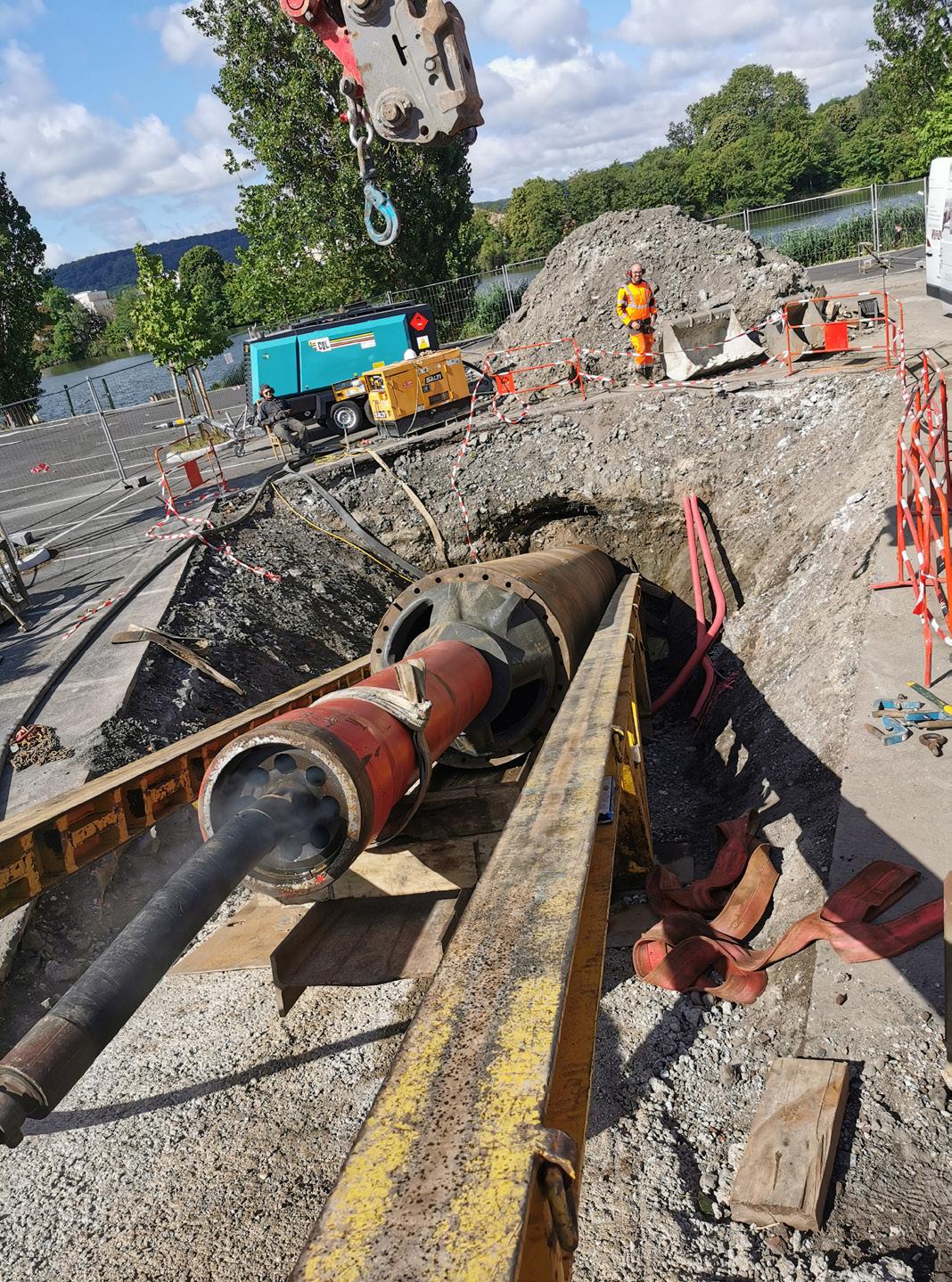
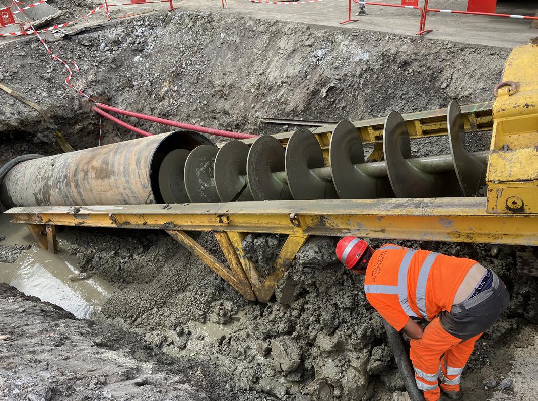
HDD drilling operations: these so-called HDD Assist & Rescue methods can, for example, support the pipe pull-in with dynamic impact force, loosen stuck drill pipes or, as in Pont-à-Mousson, ram steel casing pipes through nondrillable soils in order to start and end the horizontal bore.
FNO’s Goliath is already 12 years old but has lost none of its 18 600 Nm impact force. To enable the pipeline to
be installed under the Moselle in the soft riverbank soil, a 30 m long, spirally welded steel pipe with a diameter of 1220 mm and a thickness of 12.5 mm had to be driven into the ground at an angle of 30° on both sides of the Moselle.
To do this, Forages du Nord-Ouest’s experienced staff lifted 6 m long pipes into the trench, welded them together and then drove them into place. This was done using a double T-beam to guide the pipe. The necessary pressure and alignment of the pile driver to the steel pipe was provided by an excavator, which pulled the pile driver to the pipe using a sling. This worked very quickly, so that advance speeds of up to 20 m/h could be achieved.
Finally, an auger boring machine was used to remove the soil around the newly installed pipe. After only three days, the soil was removed from both pipes, although some of them had to be reworked, i.e. cut open and re-welded, which was certainly due to the many years of experience of the company carrying out the work. Everyone involved was satisfied with the professionalism of this HDD assist operation.
Gentle network expansion thanks to trenchless technology
Once the casing pipes were ready on both banks of the river, the actual installation of the district heating pipeline under the Moselle could take place in October. The first step was to use the HDD drilling rig to create a pilot bore along the route, starting through the casing pipe on the right bank and exiting through the pipe on the left bank. In a second step, the bore channel was widened to accommodate the district heating pipe with a diameter of 600 mm. Finally, the pre-insulated pipe, which is almost 300 m long and weighs 10 t, is pulled into the widened trench in one piece. It will run 40 m below the water level.
In total, Pont-à-Mousson’s district heating network is currently being extended by 10 km, including new pipes in the town centre. The first phase, which was commissioned in 2015, already covered 10 km on the right bank. Trenchless technology has now made it possible to extend the network on the left bank of the Moselle in a gentle and sustainable way.
Collaboration delights the client
The project was completed on schedule at the end of October, much to the client’s pleasure. Sylvain Gendry, Managing Director of Groupe Gendry, was delighted: “This project is a great success for our group, which specialises in directional drilling and trenchless construction in general. The two special features of this project were the construction of two casings on the one hand and the construction of a river crossing over a relatively short distance of 330 m on the other hand. The good cooperation between Gendry and FNO has shown that French companies are able to join forces for the most complex projects. We would like to thank everyone involved in this project, from our suppliers to our end customers.”
Figure 2. A double T-beam ensures safe guidance of the rammer in the soft bank soil. The add-on cone connects the Goliath firmly to the steel pipe.
58 World Pipelines / APRIL 2024
Figure 3. Once the ramming is done, the accumulated soil is removed from the casing pipe using an auger drill.



50,000

5,000
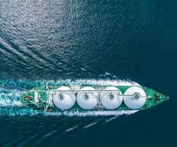
1,000
125

Supported by: Host City: Organized by: Transforming energy through vision, innovation and action
is the largest energy exhibition and conference for natural gas, LNG, hydrogen, climate technologies, low-carbon solutions and energy manufacturing - providing the defining answers of the coming decades as the world decarbonizes its energy system. FIND OUT MORE Climatetech zone Decarbonizing the energy value chain
Gastech
800 20 Attendees Exhibitors International country pavilions
Speakers
Delegates
Countries
Ministers and global energy CEOs Hydrogen zone Accelerating hydrogen’s role in the global energy mix Shipping and Marine zone Investing in LNG infrastructure and decarbonizing the marine value chain Gastech 2024 show floor features include: gastechevent.com
500
Alessandro Terenzi, Giorgio Arcangeletti, Enrico Bonato, Elvira Aloigi, Lorenzo Maggiore, and Annalisa Di Felice, Saipem S.p.A., offer an overview of the challenges and opportunities for CO2 pipelines in the energy transition, drawing on offshore and onshore case studies.
The global energy system is undergoing a profound transformation as the world strives to reduce greenhouse gas emissions and mitigate climate change. Renewable energies, such as wind and solar, are expected to play a major role in the future energy mix, but they also pose challenges for the stability and reliability of the grid. Hydrogen, as a clean and versatile energy carrier, can offer solutions for
systems, studies and solutions
storing and transporting excess renewable energy, as well as for decarbonising hard-to-abate sectors, such as heavy industry and transport.
Carbon Capture, Utilisation and Storage (CCUS) technologies can also help reduce the carbon footprint of fossil fuels, especially natural gas, which can serve as a flexible and lowcarbon backup for variable renewables. CCUS involves capturing
61
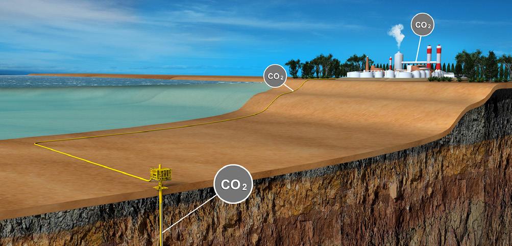
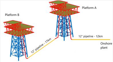

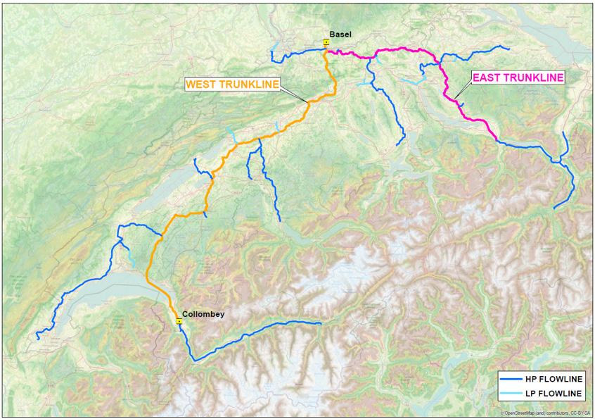
the carbon dioxide (CO2) emitted from power plants or industrial facilities, transporting it to a suitable location, and either utilising it for various products, such as chemicals, fuels, or building materials, or storing it permanently in geological formations, such as depleted oil and gas fields or saline aquifers.
Pipelines can play an essential role in the implementation of CCUS, by providing a safe and reliable way of transporting large volumes of CO2 from capture sites to utilisation or storage sites.
Pipelines can also enable the development of regional and international CCUS networks by connecting different sources and sinks of CO2 and facilitating cross-border trade. However, pipelines need to be designed and operated to handle CO2, as it has different physical and chemical properties than natural gas, such as higher density, higher corrosivity, and more complex operating phase envelope characteristics. This can be done by retrofitting existing natural gas pipelines, or by building new dedicated CO2 pipelines, depending on the technical and economic feasibility.
For years, Saipem has played an active role in the development of technologies and solutions for the safe and reliable transportation of CO2 via pipelines. This article will illustrate a couple of design cases, namely: a repurposing exercise applied to an existing sealine system to transport CO2 offshore and conceptual studies for new on-land CO2 pipeline transportation.
Repurposing existing sealines to CO2 transport offshore: a case study
The design of offshore pipelines for CO2 transportation is a relatively new topic, which requires specific knowledge and skills. The main aspects that differentiate CO2 pipelines from conventional hydrocarbon pipelines are the following:
) The fluid properties and phase behaviour, which depend on the CO2 composition, purity, temperature, and pressure. CO2 can exist in gas, liquid, or supercritical state, with different densities, viscosities, and compressibility. Moreover, CO2 can form solid hydrates under certain conditions, which can pose operational challenges and safety risks.
) The corrosion phenomena, which can affect the pipeline’s integrity and durability. CO2 is a highly corrosive agent, especially when water is present in the stream. Therefore, the pipeline material selection, coating, cathodic protection, and corrosion inhibitors are crucial aspects to consider in the design and operation of CO2 pipelines.
) The decompression behaviour, which influences the fracture propagation and arrest mechanisms. CO2 undergoes a rapid pressure drop and temperature decrease during decompression, which can lead to brittle or ductile fracture initiation and propagation along the pipeline. The decompression behaviour depends on the fluid properties, the pipeline geometry, and the initial and final pressure and temperature.
The development of a case study for repurposing existing offshore pipelines to CO2 transport, as part of a carbon capture and storage (CCS) project, needs to cover as minimum:
) The conceptual steps for the requalification of an existing pipeline system.
Figure 1. Schematics of a CO2 transport and injection offshore system.
Figure 2. Schematics of an existing offshore pipeline system repurposed to CO2 transport.
Figure 3. Schematic of a CO2 collection network in southern Italy.
62 World Pipelines / APRIL 2024
Figure 4. Schematic of a CO2 collection network in Switzerland.


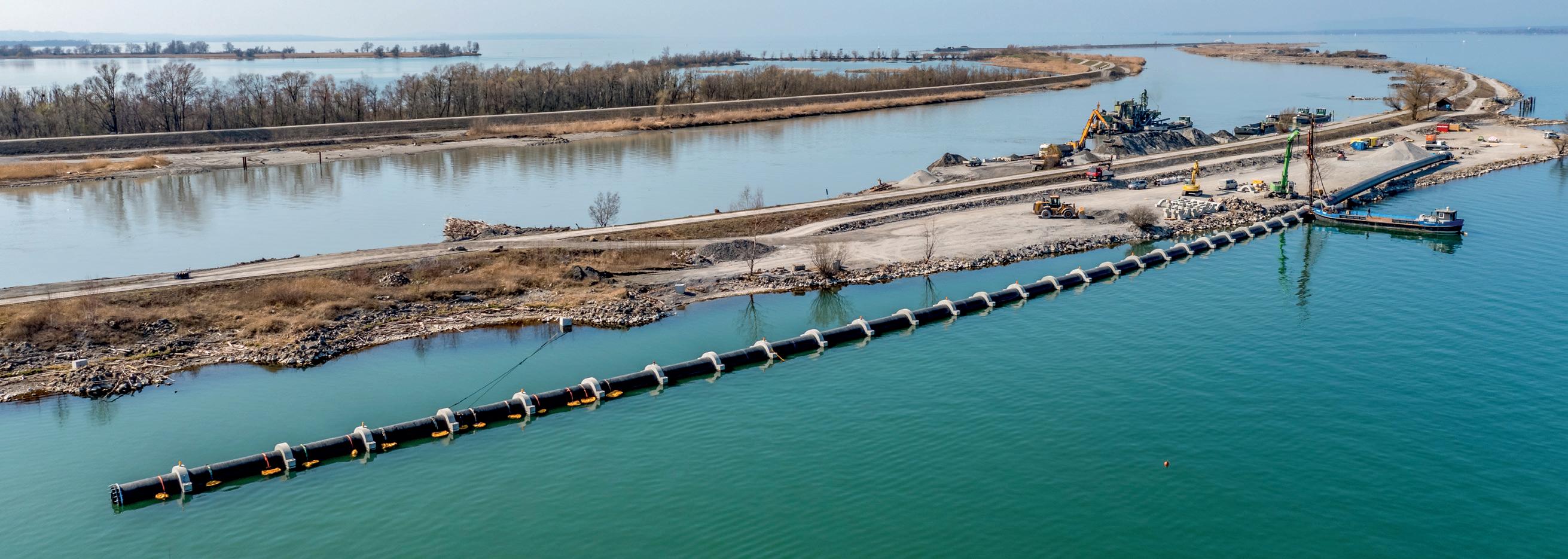
• OUTSTANDING LIFE SPAN • FAST AND EASY INSTALLATION • FOR HIGH-VOLUME FLOWS • HIGH-QUALITY MATERIALS • EXPERTISE IN PLASTICS PROCESSING AGRULINE XXL PIPES HDPE piping systems for intakes & outfalls agru Kunststofftechnik Gesellschaft m.b.H. | Ing.-Pesendorfer-Strasse 31 | 4540 Bad Hall, Austria T.+43 7258 7900 | office@agru.at | www.agru.at | @agruworld | Bild: Stiplovsek Dietmar Register for free at: www.worldpipelines.com Global midstream news, contracts and project stories World Pipelines
) The selection of design and operating conditions.
) The application of relevant standards and guidelines.
) The assessment of risks and environmental impacts.
A recent case study developed by Saipem involves two existing offshore platforms linked to shore by two 12 in. pipelines, which have already terminated their design life (Figure 2).1 The analysis considers a two-phase development process: Phase 1, where the existing pipeline is reused as much as possible to transport CO2 in gas phase; and Phase 2, where the pipeline system is replaced to transport CO2 in dense phase, due to the increase of reservoir pressure.
The main design challenges for repurposing the existing pipeline are the pressure containment and the running shear
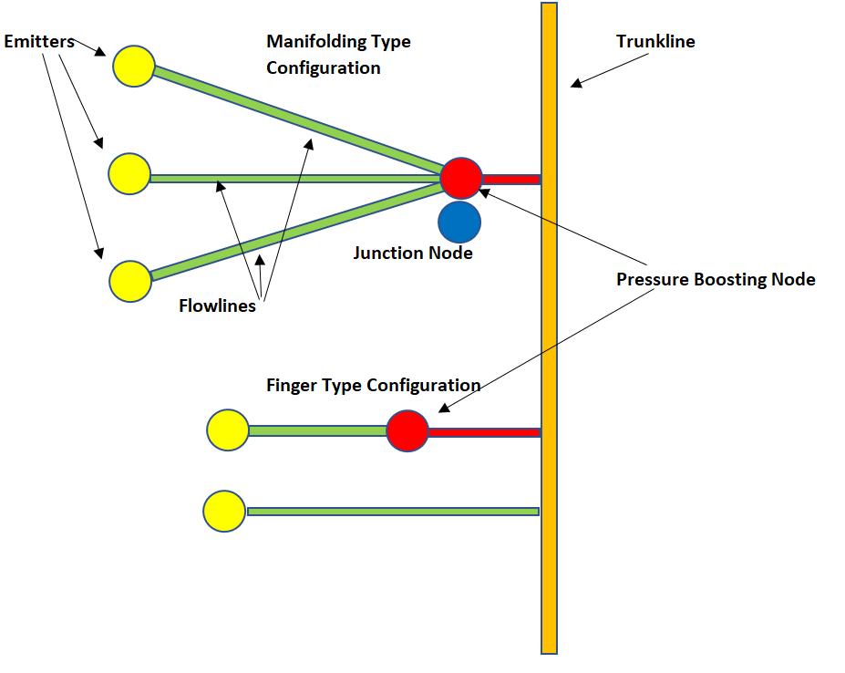
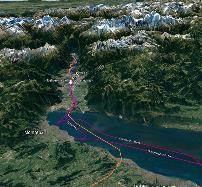
fracture (RSF) failure modes, which depend on the CO2 stream composition, the wall thickness, and the decompression behaviour.
The pipeline integrity was assessed by using different methods and criteria, and the operating conditions were selected accordingly. The ISO 27913:2016 and DNV-RP-F104:2021 standards on CO2 pipeline design both including ductile fracture control were applied.
The examined pipelines failed the running shear fracture check in case of dense/liquid CO2 transportation and a derating was required to operate in the gaseous phase. It is anticipated that this need will be common in the reuse of old pipelines.
The study also analysed the differences and uncertainties of the standards when sizing the wall thickness of the pipelines for running shear fracture arrest at dense phase CO2 transport condition, and further research and full-scale tests were recommended.
The presented case study shows the potential of repurposing existing offshore pipelines for CO2 transportation to reduce costs and environmental impacts of new infrastructure development. However, it also highlights the challenges and uncertainties that need to be addressed in the design process, especially regarding the fluid properties, the decompression behaviour, and the ductile fracture control.
Conceptual studies of new CO2 pipeline transportation networks
Saipem has built up a significant track record in CO2 onshore pipeline engineering, based on both R&D activities and feasibility/FEED studies. Some specific technological issues related to low operating temperature scenarios, as well as ductile fracture propagation have been investigated in detail. The design capabilities are in line with the state of the art in all involved pipeline engineering disciplines. While the first experiences focused on single point to point pipelines, more recent studies were performed on complex networks, characterised by the presence of multiple emitters with relevant capture and compression plants, and multiple delivery locations. For single long transmission pipelines the transport in dense phase conditions is usually more advantageous, providing lower transport costs; however, this is not always true in a complex system where several capture and compression plants are present.
Furthermore, if the pipelines cross populated territories, local constraints may affect the selection of an appropriate design pressure, thus imposing a defined phase of transport. An example of such a complex network recently studied by Saipem is shown in Figure 3, with a schematic of a pipeline system envisaged to collect and transport CO2 in southern Italy, including a coast terminal to upload it into ships for offshore transport. Another significant feasibility study has recently been carried out to identify the optimal transport configuration of a complex pipeline network in Switzerland, collecting CO2 captured by 32 large emitters spread across the country. The total annual transport capacity of this system is about 7.5 million tpy.
Two delivery points are considered: one in the area of Basel for final export to northern Europe, and one in Collombey for transmission towards Italy. Based on the emitters distribution, a system of two main trunklines collecting the CO2 up to
Figure 5. Possible configurations for the network flowlines. Nodes may include pressure boosting stations or they can be junction nodes.
64 World Pipelines / APRIL 2024
Figure 6. Lake Geneva crossing overview.
Above and below - Indonesian Buaya Besar Barge 1.2 m to 20 m depth.
World’s deepest water post trencher sled 1200 ft
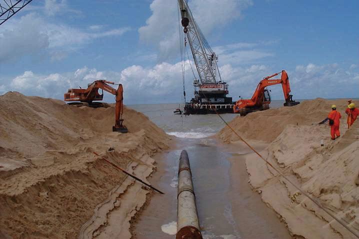
Brasil Post Trenching Rough Shore Approach (Lead Keel Machine)
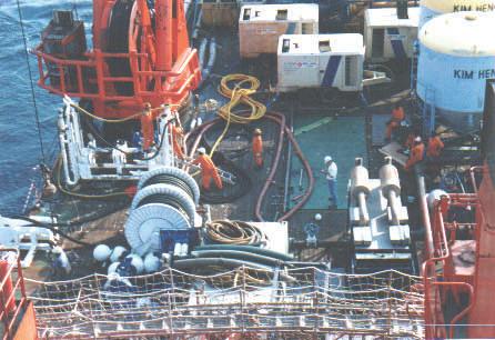
Above and below—Ultra shallow water system 0.6 m to 3 m depth.
Typical Deck Layout On DP Vessel for Deep Water Trenching 80 to 400 meters
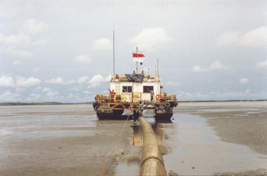
Post Trenching in rough swells off Brazil.
Post Trenching in rough swells off Brazil.
Post Trenching in rough swells off Brazil.
Cutter Suction Dredge
Cutter Suction
Cutter Suction
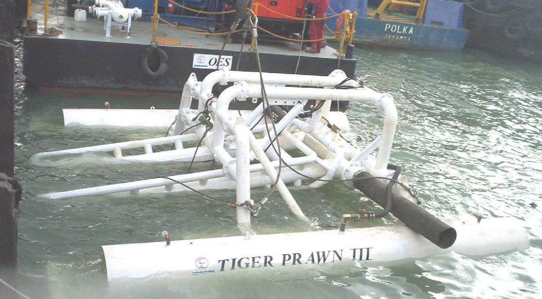
Above and below - Indonesian Buaya Besar Barge 1.2 m to 20 m depth.
TRENCHING CAPABILITES

Above and below—Ultra shallow water system 0.6 m to 3 m depth.
OES INTERNATIONAL LOCATIONS
Diverless Systems
Above and below - Indonesian Buaya Besar Above and below—Ultra shal system 0.6 m to 3 m depth.
Above and below - Indonesian Buaya Besar Above and below—Ultra shallow water system 0.6 m to 3 m depth.
Above and below - Indonesian Buaya Besar Above and below—Ultra shal system 0.6 m to 3 m depth.
OES World Leader in Subsea Pipeline Trenching Is For Sale (all assets tangible and proprietary intangible) Track Record since 1992 includes the successful trenching of over 250 pipelines and cables including the following world’s firsts:
• Largest Pipeline 54 inch 1995 India
DP vessels
First Trenching by Dynamic Positioned Vessel 1992 New Zealand
• Trenching in largest Seas 28 ft 1992 New Zealand
Trenching Hardest Soils with proprietary high pressure system 150 kpa shear strength Thailand 1993
Busan, Korea
working off DP vessels
vessels
• First and only Post Rock Trencher ‘Tiger Shark’ 1994 to 2008
Key Largo, USA
Trenching Deepest Pipelines 400 meters 1999 Bass Strait
working off DP vessels
Trenching Deepest trench 7 meters 2000 Indonesia
• Trenching in strongest water current 11 knots China 2004
Trenching Stress Relieving of Directional drilled pipelines by others Australia 2004
• Trenching Live Gas Pipelines Indonesia 2006
.
Singapore
Trenching roughest shore approach with pumps on beach Ghana, Africa 2018
Rio De Janeiro, Brazil
Seychelles Islands
Balikpapan, Indonesia
• Also laid 7 kilometers of 150 NS 110,000 Volt cables including directional drilling shore approach through rock cliffs
• Salvaged six projects where pre dredging, directional drilling and jet sleds failed
Melbourne, Australia
Corporate Headquarters
Equipment Includes: 45 20 ft sea freight containers with 8 x 1600 hp 350 psi pumps, 2 x 1000 psi booster pumps, 3 hydraulic hose reels with 90 to 120 meters of 4 x 4 inch hose, interconnecting piping and suction strainers, 6 x subsea pipeline lead keel type jet machines for 6 inch to 52 inch pipelines, Arabian Leopard, White Jaquar, Bengal Tiger, Tasmanian Tiger, and Sumantran Tiger, 1 Tiger Shark cuts 600 mm deep trench per pass x 1200 mm wide in 30 mpa ucs rock, 2 cable trenchers that simultaneously backfill to 1.5/3 meters cover. An eight point mooring system 20 tonne, 20 tonne heave compensator, 3 Hydraulic power packs including 1 300 HP for tiger Shark, 1 Tiger Shark Hose reel with 2 x 500 meters of 5000 psi hydraulic hose and a 10 tonne clump weight and deployment system. A 10 tonne hydraulic cable tensioner.

Company Value 1995 to 2014 $100 million. Sell now $5 million or best offer. Ask for photos, specs, container lists and completed project references.
INTERNATIONAL OIL, GAS AND POWER EPC CONTRACTOR • • • • • •
•
1 305 304 6452 www.oes.net.au lincolnoes@aol.com
Typical Dynamic Positioned Vessel during Trenching (Lead Keel Machine)
Inter Tidal trenching in mud flats 1.2 m to 20 meters (Lead Keel Machine)
Floating Jet Sled across mud flats too shallow for barge
the delivery points has been outlined. The East Trunkline is connected to Basel and it can operate in one direction only, whereas the West Trunkline connects Collombey to Basel and it can operate in both directions (Figure 4).
Two main transport options have been considered regarding the phase of transport: gaseous transport, with design pressure limited to 40 barg, and dense phase transport, with design pressure of 150 barg.
Due to the possible maximum operating pressure constraints in densely populated areas, the transport network could be operated in a mixed mode, with single flowlines operated in gaseous phase, connected to large trunklines operated in dense phase. Each emitter is connected to the main trunkline by means of a dedicated flowline. Two different options are identified to connect the flowlines to the trunkline (Figure 5):
) Manifold-type configuration: a group of flowlines (usually close to each other) are collected in a manifold and then connected to the trunkline with a single line.
) Finger-type configuration: each emitter is directly connected to the trunkline with a dedicated flowline.
The CO2 supplied from the emitters by their capture units is wet at atmospheric conditions. Dehydration units could be installed either at the emitter (decentralised dehydration) or at the system manifolds (centralised dehydration). In case of centralised dehydration, plastic pipes could be considered to transport the wet CO2 up to the manifold avoiding the corrosion issues that would arise using carbon steel pipes.
However, if the CO2 enters the pipeline at saturated conditions, the relevant operating curve crosses the water formation region, leading to free water condensation in the line. The relevant flow analysis, showing the possible occurrence of slugging issues, drove to the selection of carbon steel pipes for low pressure flowlines, which requires decentralised dehydration of the CO2 to avoid corrosion issues. This conclusion was also strengthened by the fact that no significant savings were estimated by using plastic instead of carbon steel, due to large plastic wall thickness requirements for the considered operating pressure conditions.
The proposed compressor type for the system is called ‘integrally geared compressor’, that is characterised by the presence of multiple stages of compression, each having a proper independent regulation of the rotational speed of its shafts and impellers. Furthermore, it is characterised by a simpler intercooler implementation with respect to traditional inline compressors. These characteristics allow for a better compression efficiency and reduced power consumption. The compression system is integrated with the dehydration equipment, considered as using the molecular sieve technology.
Special routing analysis has been performed for specific locations; for instance, in the Zurich urban area, the connection of three emitters, by means of low-pressure flowlines is envisaged. In that area, it is possible to use the existing ‘energy tunnel’ (i.e. a 6 km long large concrete channel installed below ground), crossing the city centre, where it is possible to accommodate the flowline system.
Another specific investigation has been performed for the crossing of Lake Geneva, having a maximum water depth of 280 m (Figure 6). The need for a large diameter pipeline installation in deep water requires an ‘offshore’ design approach and availability of high-capability equipment (lay barge marine type); a dedicated installation procedure was studied for the scope.
Finally, two main transport configurations were identified, having two main trunklines collecting the overall CO2 flow from the different emitters and conveying it up to the delivery locations. Several flowlines connect single emitters or small groups of emitters to the main pipelines. In the first transport configuration, a gas only flow condition was assumed, while a mixed dense phase/gas phase transport was considered for the second one (dense phase was assumed in the main trunkline and in unconstrained flowlines). The main trunkline size was 30 in. for the gas transport option, and 14 in. - 16 in. for the dense phase one. The total pipeline length is about 1000 km, and the total compression power is 155 MW for the gas option and 230 MW for the dense phase option.
The two alternatives have been compared using a levelised cost approach, based on the evaluation of CAPEX & OPEX costs for the entire system lifetime, and expressed by a transport cost index per unit of transported CO2 mass. It was found that the transport cost of the network system alone is lower for the gas only configuration, essentially due to lower compression energy costs. However, when also considering the presence of the export compression stations, delivering CO2 to long transmission pipelines assumed to operate in dense phase, the dense phase transport overall configuration results slightly more convenient. This is due to higher compression requirements in the export stations when fed by the gas domestic network.
This case study demonstrates that the optimal selection of a complex pipeline network requires a careful analysis of all the system components and the consideration of the geo-morphological characteristics, especially in a country having many environmental constraints as Switzerland. The economical investigation requires a proper evaluation of operating costs; for the analysed system, the dense phase transport option resulted slightly more convenient, however the final selection will require a full environmental impact study to supplement the techno-economical findings.
Conclusions
Significant design experiences have been carried out by Saipem, concerning existing or new CO2 pipelines. Several technological topics have been investigated to provide robust and reliable CO2 transport systems and solutions have been identified even for critical aspects such as transient low temperatures operation or potential ductile fracture propagation. Designs for onshore and offshore transmission pipelines, both for new systems as well as repurposed ones, must be properly developed in order to fit with most CCUS technologies.
References
1. MARCHESANI, F., LEPORINI, M., TORSELLETTI, E., ORSELLI ,B., SCARSCIAFRATTE, D., MERCURI, A., and ALOIGI, E., (Saipem S.p.A.) DI BIAGIO, M., and FONZO, A., (RINA Consulting - CSM S.p.A.), ‘A case study for repurposing existing sealines to CO2 transport offshore’ – presented at OMC 2023, Ravenna, Italy.
66 World Pipelines / APRIL 2024

ABC. See it. Believe it. Trust it. To advertise email Chris Lethbridge at chris.lethbridge@worldpipelines.com or Daniel Farr at daniel.farr@worldpipelines.com

Neil Skene, Operations Manager, Imrandd Ltd, UK, discusses optimising offshore asset integrity through advanced data solutions.
68

he efficient management and maintenance of offshore assets is increasingly critical for sustained operations and long-term viability in the energy sector.
Integrity assessments play a crucial role in ensuring the prolonged and reliable operations of offshore installations with minimal intervention throughout their lifecycle. Oil and gas platforms, wind farms, and subsea infrastructure, are all exposed to harsh environmental conditions and complex challenges, making regular inspections essential for maintaining their integrity and functionality. The goal of these assessments is to minimise the need for disruptive interventions that could lead to downtime, and therefore increased costs and potential safety risks.
The sorting and curation of data is playing an increasingly important role, providing insights which support more effective safety-critical equipment maintenance planning, while reducing the requirement for unnecessary inspections. However, there are a number of hurdles to overcome to gather and extract full value from the available data. This is partly due to the extreme volume of data which can span decades for mature assets, including information from various different sources. The existing approach in large physical asset management revolves around sporadic
69
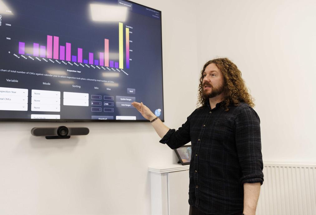
data collection, periodically analysed by humans. This method results in reactive and lagging decision-making, where the full commercial picture is not always considered, which can lead to operational disruptions and further technical, operational and logistical complexities if not addressed.
However, these challenges highlight opportunities for change where digitalisation is a key player. Advanced data analytics, artificial intelligence and the Internet of Things (IoT) empower operators to optimise production, predict equipment failures, and streamline maintenance processes. The digital transformation of fields can enhance safety and environmental stewardship, extending the operational lifespan. To fully leverage the potential of data, it is imperative for the energy industry to ensure robust data management and integrity.
Extending operational life
Imrandd specialises in industrial data solutions, helping clients in energy and other sectors to make fast and efficient business decisions in line with commercial and environmental, social and governance (ESG) strategies.
The company was recently approached by a North Sea operator to carry out a comprehensive integrity assessment on a floating production storage offloading (FPSO) vessel. The FPSO was undergoing modifications and upgrades to accommodate new field operation conditions and required identification of equipment for replacement, repair or fabric maintenance. The organisation also requested details for prioritising the order in which they were replaced based on their condition. The aim was to ensure minimal need for offshore intervention from an integrity standpoint to extend the operational life of the field, up to cessation of production (CoP) in 2035.
Imrandd collaborated with a digital asset management specialist to bring combined capabilities across asset scanning, data extraction and data analysis, allowing for large volumes of inspection data to be efficiently obtained, processed, and analysed. The partnership set out to make optimal use of the FPSO’s large dataset which consisted of external asset scans and internal inspection reports.
The partner company’s web-based technology was first utilised for inspection of all pressure systems which included
pipework, vessels, heat exchangers, tanks, and filters, in addition to topside structures, hull, and marine elements. The visual inspection tool utilises accurate inspection and engineering data to rapidly detect and quantify defects, providing functionality to facilitate support and manage the integrity management cycle.
Imrandd gathered all non-destructive testing (NDT) reports including crucial integrity assessment data which was then sorted, curated and cleansed for further analysis using semiautomated QA/QC processes, before employing its EXTRACT software.
EXTRACT automatically ingests and gathers data which is essentially inaccessible, and consolidates it into one digestible format, ready for analysis. The technology utilises a combination of techniques including optical character recognition (OCR) and computer vision to enable limitless volumes of data to be processed rapidly. With the ability to pull data from multi-format sources and different report types, extraction of large datasets delivers accurate digitised data.
From the data processed, Imrandd’s proprietary solution obtained 2976 topside pipework wall thickness readings from over 480 inspection reports from 2017 onwards. This produced considerable time savings, taking a matter of days in comparison to what would have previously taken a team of engineers weeks, and ensured that there was a clear picture of the asset’s condition history.
Actionable data insights
The extracted data was then processed using Imrandd’s EXACT analytical tool which cleanses, corrects and interprets large data sets, then maps and predicts equipment degradation. It delivers actionable insights to significantly reduce OPEX and improve asset integrity management and plant reliability. Utilising these insights, corrosion rates were calculated and remaining life predictions from trendable data were identified and formed the basis for recommended inspection intervals and integrity interventions. This ensured that failure patterns and corrosion hotspots and risks were known, with the software identifying threats which were potentially unknown or reveal inspection blind spots.
EXACT provided further analysis of the data which helped to provide large scale statistics-based trending corrosion rates, and predicted the remaining operational life to ensure key maintenance priorities were identified.
Technology applications for external assessments
The next step involved an external condition assessment by integrating Imrandd’s methodology with our partner’s technology for all pressure systems, structures, hull, and marine elements. Data was gathered from master and reference sources such as the equipment register and piping specifications, and scanned data was assigned corrosion categories for each line, calculating corrosion ratesbased on operating conditions and recommended practices. Degradation calculations were applied over a timeframe lasting until COP 2035 to determine the timeframe for maximum allowable working temperature (MAWT) breach and highlighted potential threats across all topside components. The extraction collected a 100% external visual inspection report
70 World Pipelines / APRIL 2024
Figure 1. Imrandd’s advanced data solutions provide operators with valuable insights, equating to significant reductions in maintenance and repair costs.



North America’s Leading Event For Carbon Capture, Utilization & Storage www.ccus-expo.com FREE TO ATTEND REGISTER NOW Carbon Capture Technology Conference & Expo is dedicated to discussing the increasing role that Carbon Capture, Utilization & Storage (CCUS) will play in transition to a net-zero carbon economy. Leading experts from around the world will discuss the latest advances in new technology for carbon capture, storage and transport, as well as unique ways of utilizing CO2 to produce netzero fuels and for other manufacturing processes. 2023 WINNER Multi-Award Winning Show June 26-27 2024 NRG Center, Houston, Texas, USA 400+ EXHIBITORS 130,000Sq ft EXHIBITION SPACE 200+ SPEAKERS 8,000+ ATTENDEES 5 CONFERENCE TRACKS
ADVERTISERS’ DIRECTORY
and established a baseline for integrity evaluations for pipework and vessels.
Both the internal and external results were validated through a site inspection of areas of concern and unquantifiable areas with threat potential. The findings were fed back into the analyses as a means of ‘calibrating’ to ensure the most up to date actual condition was reported. This allowed optimisation of final recommendations to minimise the number of in-scope items requiring integrity action or any future in-operation inspection. The assessment at system and line level also summarised all existing and new anomalies with primary findings and recommendations and acting as a primary feed to the longerterm risk based inspection programme.
Critical integrity threats and items with limited inspection were identified, revealing that less than 4% of inspected items required repair, replacement, or urgent fabric maintenance. Internal integrity preservation actions were identified, and specific structural components within the assessment were recommended for fabric maintenance to prevent future integrity issues.
From the data acquired, cleansed and analysed, Imrandd was able to provide the operator with valuable recommendations equating to a significant reduction of 40 - 50% in anticipated maintenance and repair costs. The integration with the partner company also identified new anomalies that had previously gone uncaptured. By identifying and prioritising items for replacement, repair or fabric maintenance, the assessment allowed the business to plan and allocate resources more efficiently, ultimately extending the operational life of the FPSO.
The project also delivered a short-term remedial programme with defined repair, replace and fabric maintenance scope and long-term recommendations including targeted fabric maintenance actions to preserve asset integrity over the field’s operational life up to COP. The outcome of the project had a direct and substantial impact on operational costs, alongside a vast reduction of the anticipated maintenance, inspection, and repair activities.
Innovative solutions to support the industry
As operators strive to gain greater economical value from mature assets, advancements in data management technology are critical in supporting effective inspection and maintenance programmes. The seamless integration of advanced data solutions with digital asset management solutions, result in comprehensive assessments that far surpass the outputs of traditional methods.
The significance of data lies in its ability to provide actionable insights for effective maintenance planning and risk mitigation. With the advent of advanced innovations, the industry can effectively move beyond sporadic and reactive data collection methods, transitioning towards a proactive, data-driven approach. Data analytics not only supports the identification of potential threats but also aids in predicting equipment degradation, enabling asset owners and operators to adopt a preventative rather than a corrective stance.
Data-driven integrity management is a transformative force in the energy and industrial industries, shaping a future where assets are not only safeguarded against potential risks but are also operated with a keen eye on sustainability and long-term viability.
Advertiser Page 3X Engineering OFC, 02 ABC 67 AGRU 63 American Augers 35 BAUMA 37 Carbon Capture Technology Expo 71 Dairyland Electrical Industries 41 Darby Equipment Company 43 DeFelsko 32 DENSO Inc. 07 Deyuan Pipe IFC Electrochemical Devices 57 Gastech 2024 60 GeoCorr LLC 08, OBC Girard Industries 54 IPLOCA 20 LNG Industry IBC OES Limited 65 Pigs Unlimited International LLC 27 Pipeline Technique Ltd t/a CRC Evans 04 Propipe 44 Pipeline Inspection Company 49, 59 Qapqa 31 Seal for Life Industries 19 Stark Solutions 13 STATS Group 11 T.D. Williamson 17 Tracto Technik 47 Vermeer Manufacturing 38 Weldfit 23 World Pipelines 53, 63

A
global industry requires a global publication

Register for free at: www.lngindustry.com
Coverage
Worldwide
BUILDING THE FUTURE RENEWING THE PAST


WWW.GEOCORR.COM
TriAxial MFL Sensor Technology
Dent Strain Analysis
MFL Inspections ranging from 3” to 32”
Bend Strain Analysis
MFL CALIPER WITH IMU MAPPING


 Figure 4. Typical site installation.


