Article

Electrochemical Behavior and Electrodeposition of Sn Coating from Choline Chloride–Urea Deep Eutectic Solvents

1
School of Metallurgy, Northeastern University, Shenyang 110819, China
2
Department of Mechanical Engineering, The University of Texas at Dallas, Richardson, TX 75080, USA
3
Chinalco Shenyang Non-Ferrous Metal Processing Co., Ltd., Shenyang 110108, China
4
Institute of Metal Research, Chinese Academy of Sciences, Shenyang 110016, China
*
Author to whom correspondence should be addressed.
Coatings 2020, 10(12), 1154; https://doi.org/10.3390/coatings10121154
Submission received: 28 October 2020 / Revised: 21 November 2020 / Accepted: 25 November 2020 / Published: 26 November 2020
(This article belongs to the Special Issue Corrosion and Electrochemical Behavior of Metals Coating)

Abstract

:
The electrochemical behavior and electrodeposition of Sn were investigated in choline chloride (ChCl)–urea deep eutectic solvents (DESs) containing SnCl2 by cyclic voltammetry (CV) and chronoamperometry techniques. The electrodeposition of Sn(II) was a quasi-reversible, single-step two-electron-transfer process. The average transfer coefficient and diffusion coefficient of 0.2 M Sn(II) in ChCl–urea at 323 K were 0.29 and 1.35 × 10⁻⁹ cm2∙s−1. The nucleation overpotential decreased with the increase in temperature and SnCl2 concentration. The results of the chronoamperometry indicated that the Sn deposition on tungsten electrode occurred by three-dimensional instantaneous nucleation and diffusion controlled growth using the Scharifker–Hills model. Scanning electron microscopy (SEM) showed that the morphology of the deposits is uniform, as a dense and compact film prepared by potentiostatic electrolysis on Cu substrate. X-ray diffraction (XRD) analysis revealed that the deposits were pure metallic Sn.

1. Introduction

Tin and its alloy coatings are widely used in various industrial fields because of its high corrosion resistance, non-toxicity and good soldering properties, which has an easily soldered coating for printed wiring boards, connectors, lead frames and transistor leads, protective coating to steel sheet from corrosion, tinplates for the food industry (containers and packages), coating on copper and aluminum bus-bars to ensure good contact at joints to carry high electrical currents [1,2].
Tin and tin alloy can be electrodeposited in acidic or alkaline aqueous solution [3,4]. The acidic electrolytes mainly include sulfate, fluoborate and methanesulfonate solutions [5,6,7]. In order to improve the quality of the coating and the electrolyte stability, cyanide and organic as additive was introduced in the electrolyte. Due to the toxicity, the hydrogen discharge secondary reaction during the electrolysis process and the relatively narrow potential windows in the aqueous solution, electrodeposition of metals or alloys from deep eutectic solvents, have attracted substantial interest in recent years [8].
Deep eutectic solvents (DESs) are a new class of ionic liquids, based on combinations of choline chloride with hydrogen bond donors, such as carboxylic acids, glycols and amides [9]. Compared with aqueous electrolytes, DESs have some great properties such as wide potential window, higher conductivity, high solubility of metal salts, good thermal stability, and the absence of hydrogen evolution on the electrode, which make them suitable electrolytes for the electrodeposition of metals [10]. At present, Zn, In, Co, Bi, Sn have been prepared in choline chloride-based DESs [11,12,13,14,15], whereas Al and Fe were electrodeposited in AlCl3–urea and FeCl3–acetamide DESs [16,17].
Xue and Huang et al. have investigated the deposition of Sn from AlCl3/1–ethyl-3-methylimidazolium chloride (AlCl3/EMIC) and ZnCl2/1–ethyl-3-methylimidazolium chloride (ZnCl2/EMIC) respectively [18,19]. Pereira and Ghosh et al. used anhydrous SnCl2 and SnCl2∙2H2O as a tin source to electrodeposit Sn from ChCl–ethylene glycol, respectively [20,21]. Anicai et al. investigated the electrochemical behavior of Sn electrodeposition on various metallic substrates from ChCl–ethylene glycol and ChCl–malonic acid [22]. Salomé et al. investigated the nucleation mechanism and the kinetic parameters for the Sn deposition from ChCl–ethylene glycol, ChCl–propylene glycol and ChCl–urea [23]. However, the detailed kinetic process of electrode reaction and electrochemical behavior during Sn electrodeposition still need investigating.
In this paper, the authors aimed to study the influence of temperature and concentration of SnCl2 on the reduction behavior of Sn in ChCl–urea by cyclic voltammetry (CV). The nucleation–growth mechanism of the initial Sn deposition stages was investigated by chronoamperometry measurement. The surface morphology and crystallites of the deposit were investigated by scanning electron microscopy (SEM) and X-ray diffraction (XRD).

2. Materials and Methods

The DES solvent was prepared with choline chloride (ChCl) (Aladdin Reagent Co. Shanghai, China, 99%) and urea (Aladdin Reagent Co. Shanghai, China, 99%) with a molar ratio of 2:1. The reagents were dried under vacuum at 373 K for 12 h. The binary mixture was heated at a temperature of 373 K for 30 min until a homogeneous colorless liquid was formed. SnCl2 (Aladdin Reagent Co. Shanghai, China, 99%) was added into the ChCl–urea with constant stirring at 353 K for 6 h until the SnCl2 powder was dissolved in the solution.
Electrochemical techniques were utilized to study the deposition process. The electrochemical measurements were carried out using the electrochemical workstation (Solartron 1287A, Farnborough, UK) controlled by CorrWare software (version 3.2c). Cyclic voltammetry (CV) and chronoamperometry were performed in a three-electrode electrochemical cell. Tungsten wire with diameter of 1 mm was used as the working electrode. Platinum wire and silver wire with a diameter of 0.5 mm were used as the counter electrode and quasi-reference electrode, respectively. All the electrodes were polished with abrasive paper, washed with deionized water and dried before the measurement. All the electrodes were inserted into the solution under 1 cm.
Sn films were prepared in ChCl–urea containing SnCl2 by electrodeposition experiments. The experiments were performed at a different potential in a three-electrode system. Copper foil (1 × 1 cm2) as a substrate was used as the working electrode. The films were washed with acetone and deionized water to remove the rest of the electrolyte and dried under vacuum.
The surface morphology of the deposits on copper substrate was determined by scanning electron microscopy (SEM, Zeiss Ultra, Oberkochen, Germany) with a 3–6 kV accelerating voltage. The crystal structure of the deposits was analyzed by X-ray diffraction (XRD, Philips MRD 1800, Almelo, The Netherlands) with a Cu Kα radiation at 45 kV and 40 mA in the 2θ angular range of 10°–90° with 0.02° increments.

3. Results and Discussion

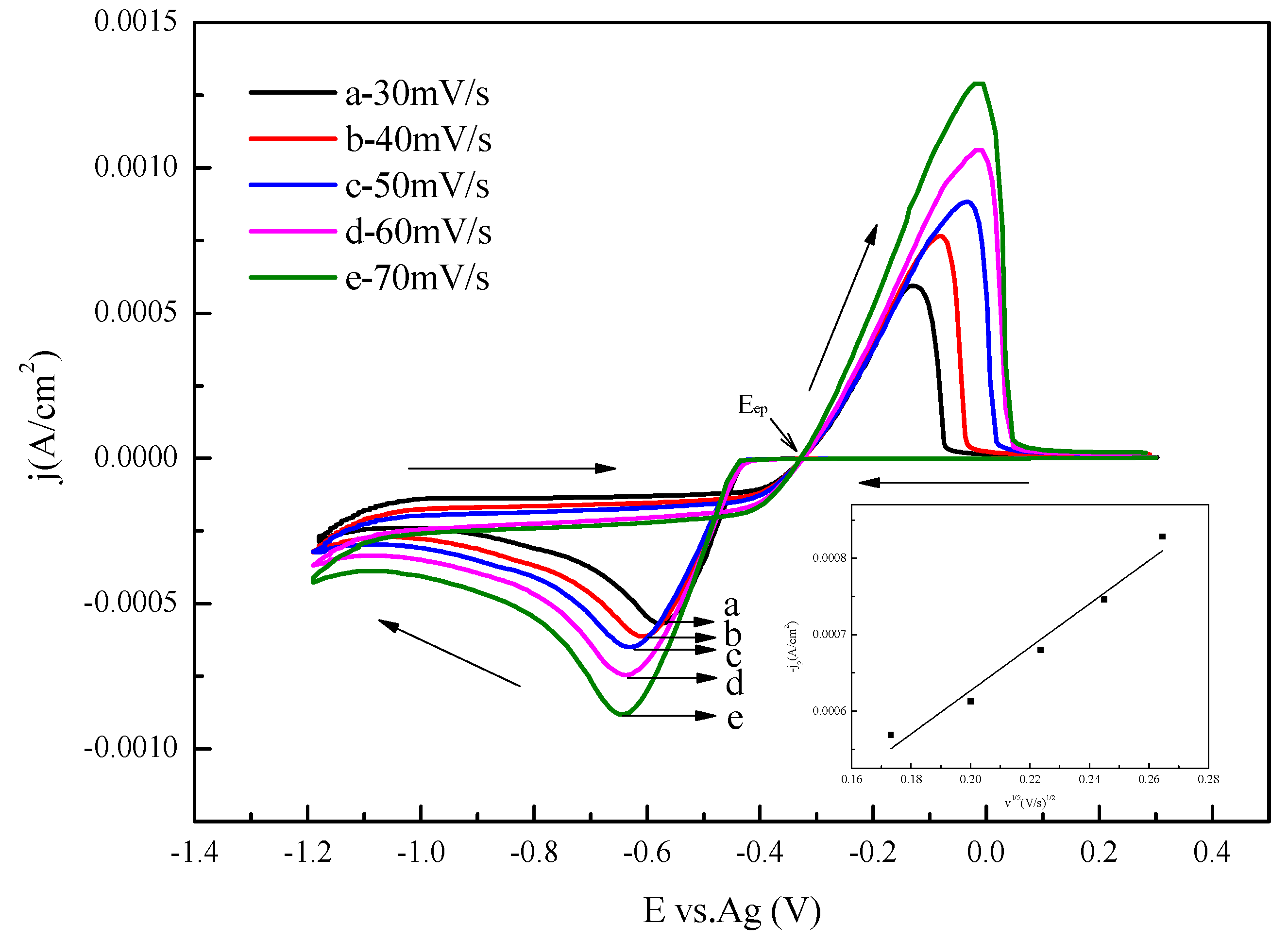
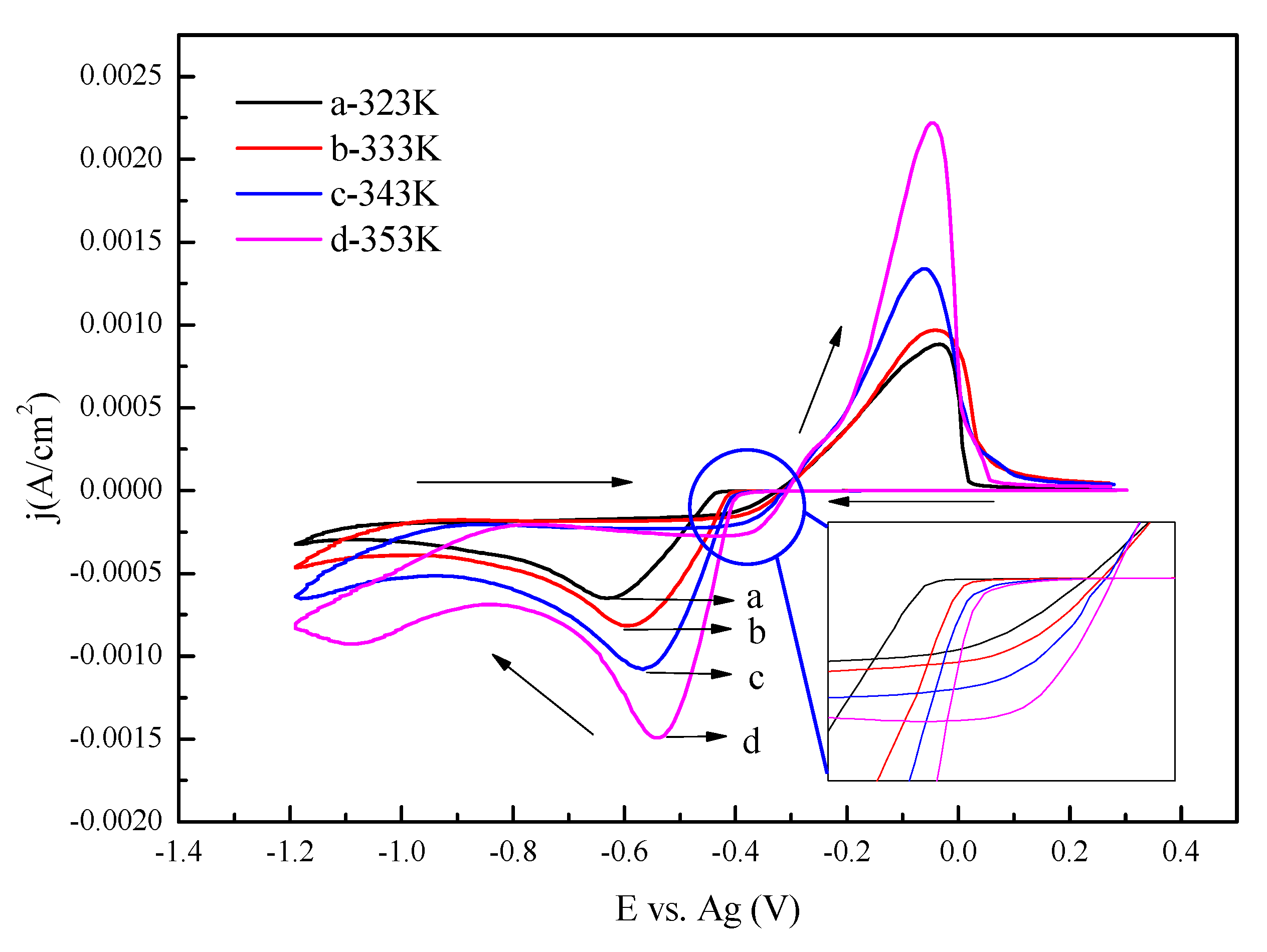
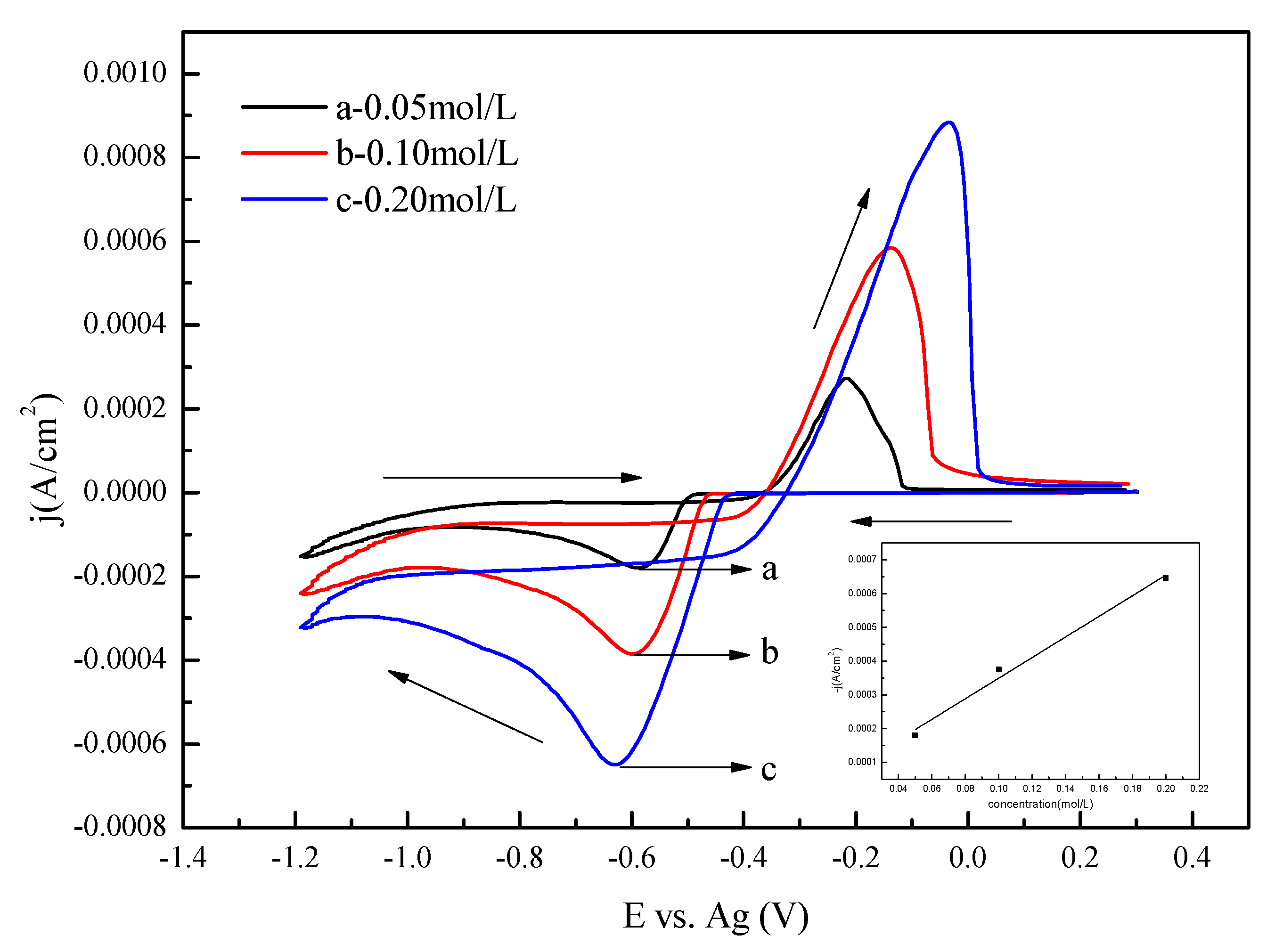
3.1. Cyclic Voltammetry

The cyclic voltammograms obtained from ChCl–urea containing 0.2 M SnCl2 solution at 323 K on a tungsten electrode, measured at different scan rates, are shown in Figure 1. It can be clearly seen that the curves display a couple of well defined cathodic and anodic peaks, which is for a typical metal deposition–stripping process. The cathodic current peak is observed at approximately −0.6 V (vs. Ag) in the forward scan. Abbott et al. reported that the Sn2+ species exists as [SnCl3] in reline [24]. Thereby, the cathodic current peak could be attributed to the reduction of Sn2+ species to metal Sn. The current increased more negative potentials than −1.1 V which was attributed to the electroreduction of choline ion [25,26].
A single anodic current peak is observed during the reversal sweep. The anodic current peak is assigned to the anodic stripping of the Sn deposit during the forward scan.
The reduction and oxidation peak potentials shift to a more negative and positive direction with the scan rate increasing, which are signs of irreversible reaction. The potential difference between the cathodic peak and half-peak potentials |Epc − Epc/2| increases with the increase in scan rate. The minimum value of potential difference is 55 mV, which is larger than the theoretical value for the reversible process (31 mV, 323 K). It was typically associated with quasi-reversible electrode reaction process [27]. The cathodic current also increases with the increase in scan rate. In addition, a good linear relationship between the cathodic peak current density (jp) and the square root of scan rate (v1/2) was obtained as shown in Figure 1 (the bottom right corner), suggesting that the reduction process of Sn(II) is the diffusion controlled adsorption process according to the Langmuir isothermal model. All these characteristics indicate that the reduction of Sn(II) is a quasi-reversible, single-step two-electron-transfer process [28].
The formular for calculating the irreversible reaction transfer coefficient is given in Equation (1). Formular for calculating the diffusion coefficient of irreversible reaction is shown in Equation (2), which is also applicable to the quasi-reversible charge transfer process:
|EpcEpc/2| = 1.857RT/(αnF)
jp = 0.4958nFc0nF/RT)1/2D1/2v1/2
where Ep is the peak potential, Ep/2 is the half-peak potential, R is the universal gas constant, α is the transfer coefficient, n is the electron transfer number, F is the faraday constant, jp is the peak current density, c0 is the concentration of metal ions, D is the diffusion coefficient, and v is the potential scan rate.
The average transfer coefficient and diffusion coefficient of 0.2 M Sn(II) in ChCl–urea at 323 K are 0.29 and 1.35 × 10⁻⁹ cm2∙s−1, calculated from Equations (1) and (2) and Figure 1.
In addition, a current crossover loop was observed between the forward and the reverse direction at a different scan rate, which means that the reduction of Sn ions requires large overpotential to form a nucleation and growth process. The prerequisite for the growth of Sn on the tungsten substrate is the formation of thermodynamically stable nuclei on the surface, which requires a more negative potential than that required to reduce Sn cations, and lead to what is known as nucleation overpotential (ηnucleation) [29]. The overpotential required initiating the first stages of the metal deposition process on the “foreign” surface of the tungsten substrate. During the forward scan, the crossover potential at a more negative potential was indicative of the formation of Sn nuclei on the electrode surface that enhanced the surface area of the electrode and decreased the activation energy for the deposition of the metal, afterward the current increase is due to the growth of first nuclei. When the scan is reversed, the reduction current continues to flow, because Sn is easily electrodeposited on a previously nucleated Sn surface than on the tungsten surface until the equilibrium potential (Eep) is reached [30,31]. It is also found the nucleation overpotential is increased by scan rate. After Eep, a notable stripping peak formed, which corresponds to the oxidation of the Sn deposit.
Figure 2 presents the cyclic voltammograms of ChCl–urea containing 0.2 mol/L SnCl2 at various temperatures (323 to 353 K). The cathodic peak current increases with increasing temperature, which corresponds to the lower viscosity and resulted in a more efficient mass transfer rate of active species and the higher conductivity of electrolyte. The reduction peak potential and the onset potential of the reduction of Sn ions shifted to more positive value (Zoom in Figure 2), indicating that the electron transfer rate increases at higher temperatures [32]. The values of nucleation overpotential (ηnucleation) are declining with increasing temperature, indicating that Sn is favorable to electrodeposit with the rise of temperature.
The cyclic voltammograms of 0.05, 0.1 and 0.2 mol/L SnCl2 in ChCl–urea at 100 mV/s are shown in Figure 3. It is observed that the cathodic and anodic peak current increases with the increase in SnCl2 concentration. In addition, a linear relationship was found between the peak current density and the concentration of SnCl2 as shown in Figure 3 (the bottom right corner), which may be due to the presence of a great amount of species available for reduction at the surface of the electrode at higher concentration, and the cathodic reduction of the electroactive species is controlled by diffusive transport [33,34]. The cathodic peak potential shifts towards a more positive value when the concentration of SnCl2 increases, indicating that the electron transfer rate increases and the higher concentration of reacting species reduced the overpotential for Sn reduction [35].

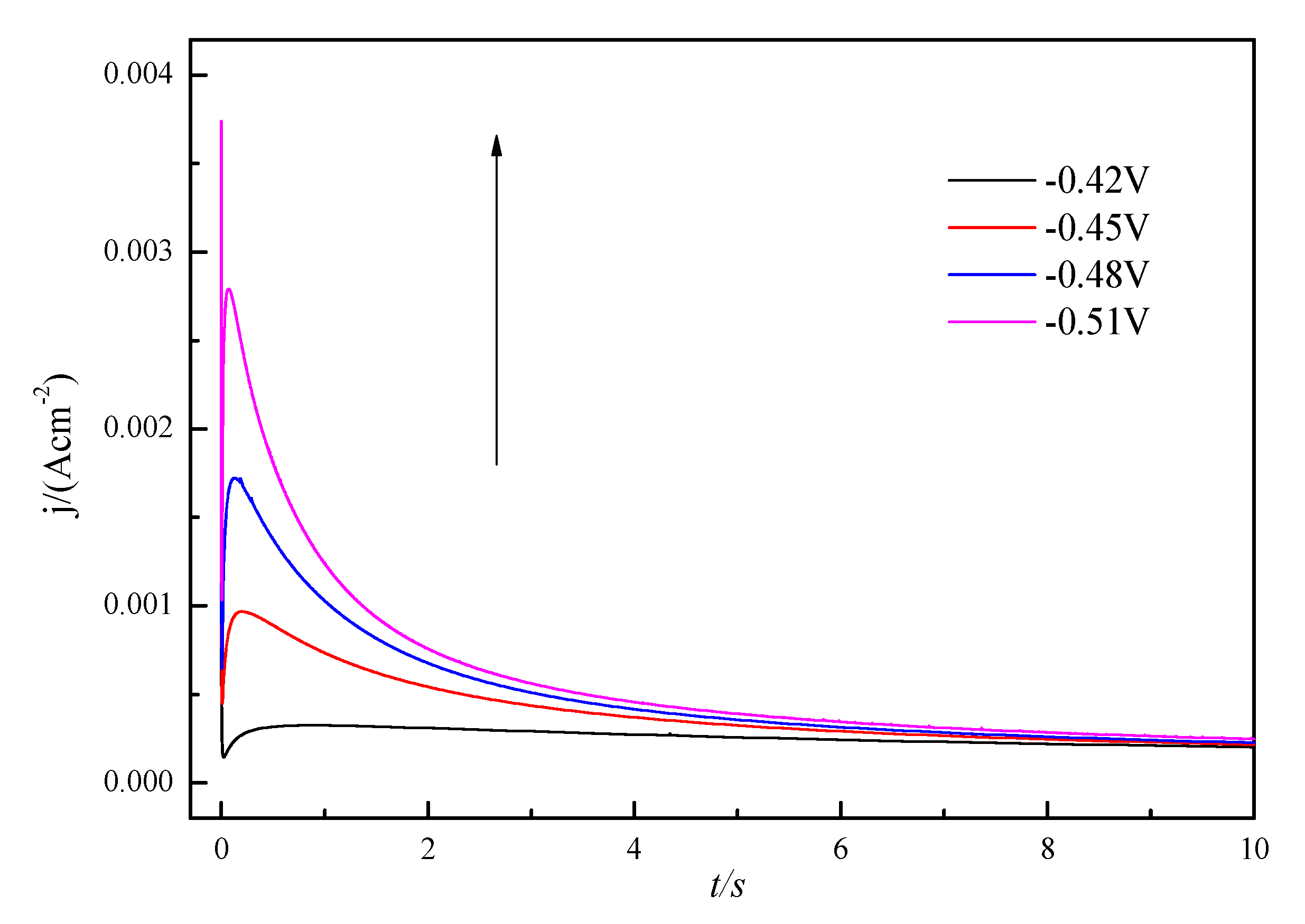
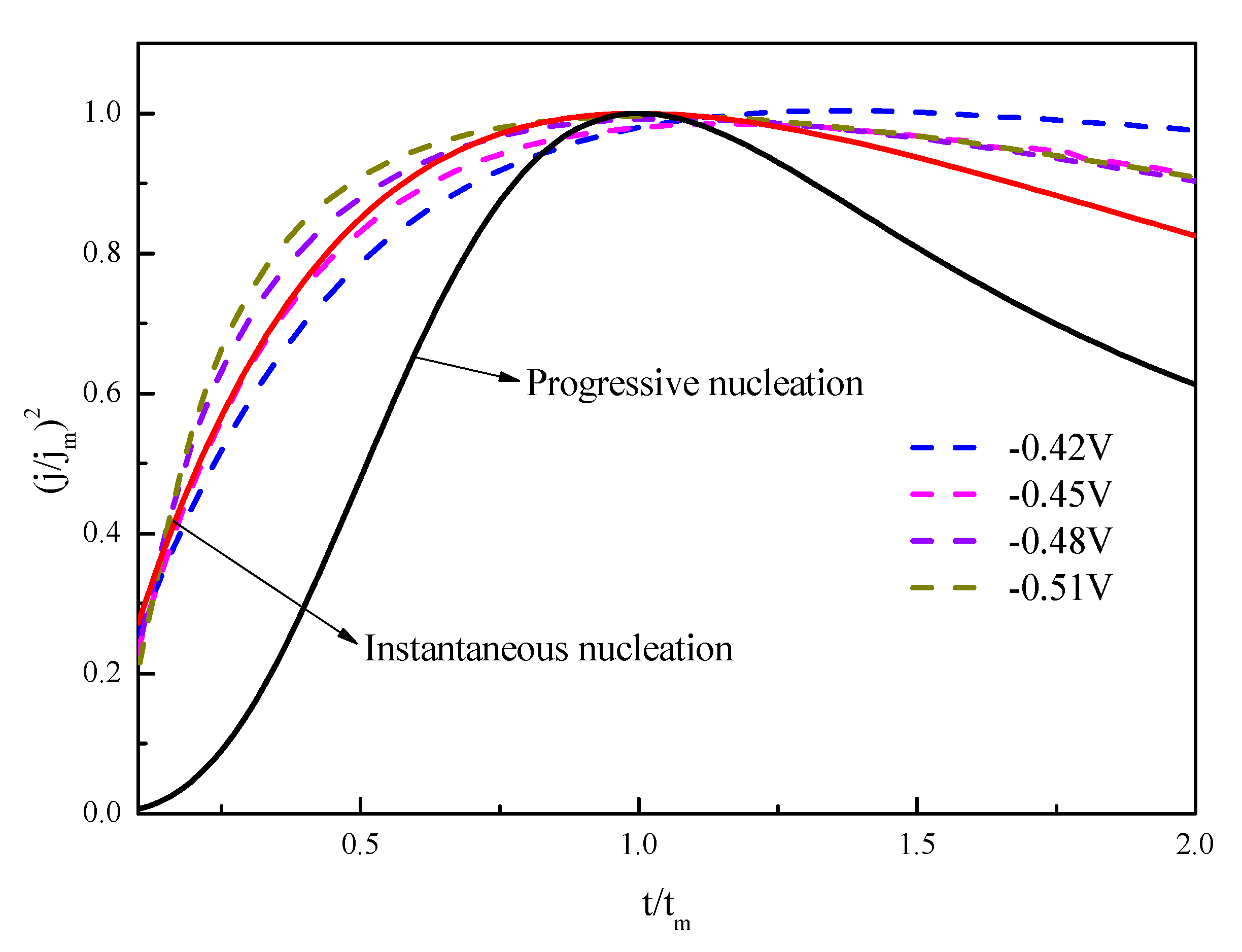
3.2. Nucleation and Growth Mechanism

The nucleation and growth mechanism of Sn deposits in ChCl–urea containing 0.2 M SnCl2 at 323 K was investigated by chronoamperometry measurement. The current density as a function of time transients obtained by stepping the potential from initial value of −0.42 V to more negative potentials (−0.45, −0.48 and −0.51 V) to initiate the nucleation and growth of Sn is shown in Figure 4.
All the curves have a similar tendency, the current density decreases because of the double layer charging. Then, the current density increases to its maximum jmax at tmax. and the sharp decreases to a constant state which have the typical characteristics of diffusion-controlled three dimensional (3-D) nucleation and growth process.
The current density increases sharply to the maximum (jmax) at a certain time (tmax) due to the growth of the individual nuclei and the increase in Sn nuclei number which increase the electroactive surface. Then, the maximum current density transients decay slowly after time tmax because of the nuclei growth centers overlap and grow toward the solution, accompanied by the disappearance of growth centers and the regeneration of new growth centers. At the stage, the current decrease is a result of the decrease in the effective electrode surface area which corresponds to the linear diffusion to the planar electrode surface [36]. The time corresponding to the jmax decrease when the applied cathodic potentials increased from −0.42 to −0.51 V is attributed to the increase in nucleation density and nucleation rate.
Scharifker and Hills developed two limiting models, the progressive nucleation and instantaneous nucleation, to identify the nucleation mechanism of metal electrodeposition [37]. For an instantaneous nucleation, the rate of nucleation was rapid in comparison with the rate of crystal growth. Nuclei are formed at all possible growth sites within very short times.
While for progressive nucleation, the rate of nucleation is slow and nuclei are generated at the surface during crystal growth. The models for instantaneous and progressive nucleation, followed by three-dimensional diffusion limited growth, are given by Equations (3) and (4), respectively.
j 2 j max 2 = 1.9542 ( t m t ) [ 1 exp ( 1.2564 t t m ) ] 2
j 2 j max 2 = 1.2254 ( t m t ) [ 1 exp ( 2.3367 t 2 t m 2 ) ] 2
where jmax and tm are the current density and time coordinates of the current–time transient curve peaks, respectively.
The comparison of the experimental plots with the theoretical curves is illustrated in Figure 5. It is obvious that the experimental data of Sn nuclei was in good agreement with the theoretical curve for the three-dimensional instantaneous nucleation and growth mechanism. However, when t/tm > 1, the (j/jm)2 was higher than the theoretical value at various cathodic potentials, which was related to the partial kinetic control of the growth process, the coarse electrode surface provide more active nucleation sites for the electro-crystallization of metal ions [38].

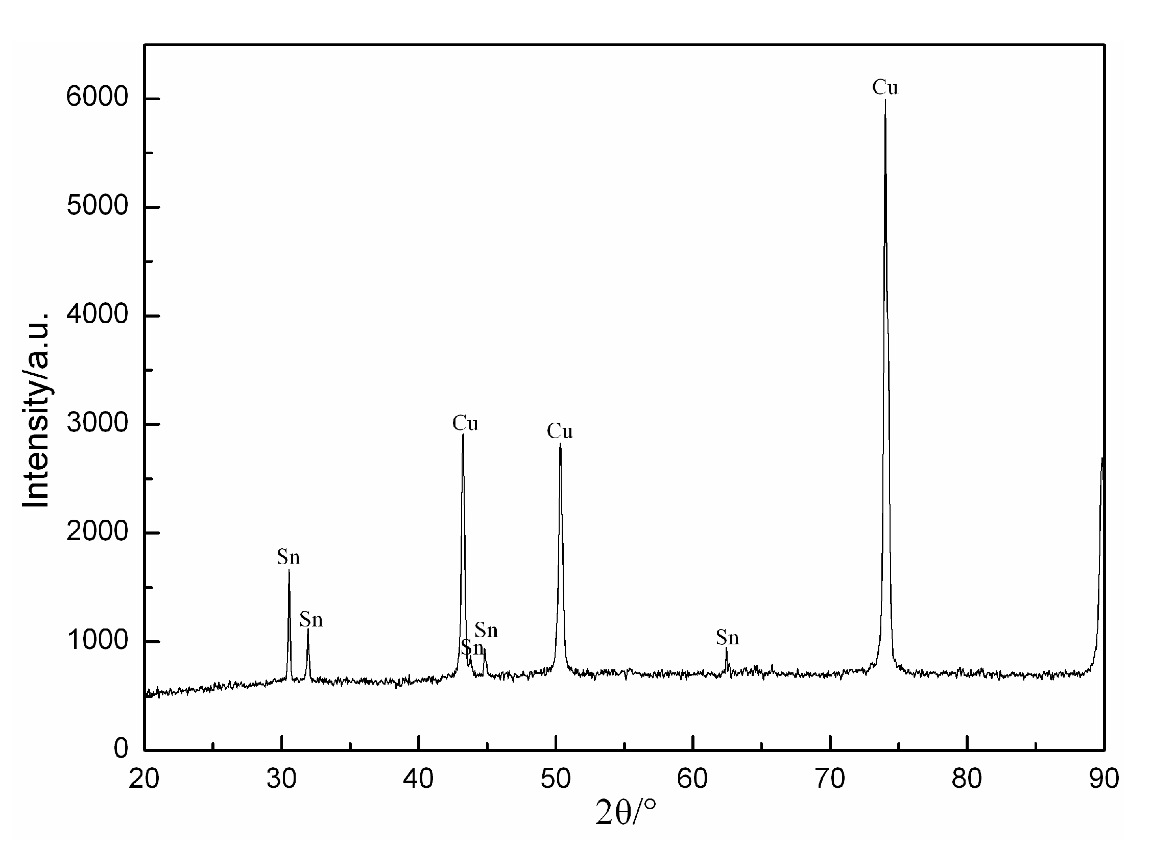
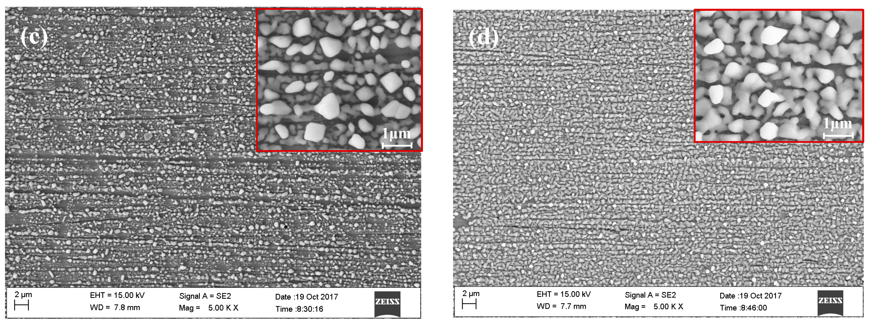
3.3. Phase Composition and Morphology of Sn Coating

Based on the above CV studies on tungsten electrodes, Sn thin film were electrodeposited on a copper substrate under conditions of controlled potential (−0.60 V) at a constant temperature of 323 K for 120 s. Figure 6 is the X-ray diffraction pattern of the Sn electrodeposits on the Cu substrate obtained from 0.2 M SnCl2 in ChCl–urea based DES. The results indicated that only two metallic phases, and all peaks correspond to the Sn and Cu substrate. No other peaks were discovered, suggesting that the main phase of the electrodeposits is Sn.
Figure 7a–d show the SEM micrographs of the electrodeposits obtained on the Cu substrates at different potentials (−0.45, −0.50, −0.55, −0.60 V) in ChCl–urea. It can be seen that lots of uniform and small particles were obtained at −0.45 V with large uncovered areas of the substrate in Figure 7a, which is attributed to the low superficial diffusion and difficulty nucleating at the low potentials. With the increase in cathodic potential, the particles have a similar morphology, which indicate that Sn deposition obeys the rule of instantaneous nucleation and growth mechanism. In addition, the particles became smaller, non-regular and were more densely distributed. When the potential is −0.60 V, the particles are compact and have entirely covered the Cu metallic substrate, as shown in Figure 7d. The nuclei population density increased, which may due to the increased number of growth sites and deposition rate.

4. Conclusions

ChCl–urea containing SnCl2 was used as an electrolyte for the electrodeposition of Sn. Cyclic voltammograms and chronoamperometry showed that for a single redox couple corresponding to the cathodic deposition and anodic dissolution of Sn, the electrodeposition of Sn was a diffusion-controlled process via a one-step, two-electron transfer process and followed an instantaneous nucleation–growth mechanism. Sn is favorable to electrodeposit with the rising of temperature and SnCl2 concentration. SEM indicated that the deposits became compact on the Cu substrate with the increase in cathodic potentials. The film electrodeposited at −0.60 V presented grains uniformly distributed and a size less than 1 μm on the surface. The XRD pattern revealed the presence of the Sn phase on Cu substrate. Further investigation can be done in order to enhance the surface morphology of the deposit considering the applications of Sn.

Author Contributions

Investigation, X.C., L.X., and S.L.; data curation, Y.S. and F.L.; resources, D.W.; writing—review and editing, X.C. and C.W.; supervision, X.X. All authors have read and agreed to the published version of the manuscript.

Funding

This research was funded by National Natural Science Foundation of China, grant number 5120403, 51804070.

Conflicts of Interest

The authors declare no conflict of interest.

References

  1. Dean, R.R.; Thwaites, C.J. Tinplate and tin coating technology. JOM 1987, 39, 42–45. [Google Scholar] [CrossRef]
  2. Azpeitia, L.A.; Gervasi, C.S.; Bolzán, A.E. Electrochemical aspects of tin electrodeposition on copper in acid solutions. Electrochim. Acta 2019, 298, 400–412. [Google Scholar] [CrossRef]
  3. Walsh, F.C.; Low, C.T.J. A review of developments in the electrodeposition of tin. Surf. Coat. Technol. 2016, 288, 79–94. [Google Scholar] [CrossRef] [Green Version]
  4. Ye, B.; Kim, S. Study on the thermal treatment conditions for fabricating open-cell structure Cu–Sn alloy foams. J. Alloys Compd. 2021, 853, 1–10. [Google Scholar] [CrossRef]
  5. Gupta, A.; Srivastava, C. Nucleation and growth mechanism of tin electrodeposition on grapheme oxide: A kinetic, thermodynamic and microscopic study. J. Electroanal. Chem. 2020, 861, 1–10. [Google Scholar] [CrossRef]
  6. Wu, L.; Cobley, J. Investigation into the effects of magnetic agitation and pulsed current on the development of Sn–Cu alloy electrodeposits. Thin Solid Film. 2019, 683, 118–127. [Google Scholar] [CrossRef]
  7. Low, C.T.J.; Walsh, F.C. The stability of an acidic tin methanesulfonate electrolyte in the presence of a hydroquinone antioxidant. Electrochim. Acta 2008, 53, 5280–5286. [Google Scholar] [CrossRef]
  8. Alesary, H.F.; Ismail, H.K.; Shiltagh, N.M.; Alattar, R.A.; Ahmed, L.M.; Watkins, M.J.; Ryder, K.S. Effects of additives on the electrodeposition of Zn–Sn alloys from choline chloride/ethylene glycol-based deep eutectic solvent. J. Electroanal. Chem. 2020, 874, 1–11. [Google Scholar] [CrossRef]
  9. Abbott, A.P.; Capper, G.; Mckenzie, K.J.; Ryder, K.S. Deep eutectic solvents formed between choline chloride and carboxylic acids:  Versatile alternatives to ionic liquids. J. Am. Chem. Soc. 2004, 126, 9142–9147. [Google Scholar] [CrossRef]
  10. Abbott, A.P.; Capper, G.; Davies, D.L.; Rasheed, R. Ionic liquids based upon metal halide/substituted quaternary ammonium salt mixtures. Inorg. Chem. 2004, 43, 3447–3452. [Google Scholar] [CrossRef]
  11. Ismail, H.K. Electrodeposition of a mirror zinc coating from a choline chloride-ethyleneglycol-based deep etutectic solvent modified with methyl nicotinate. J. Electroanal. Chem. 2020, 876, 1–10. [Google Scholar] [CrossRef]
  12. Bohlen, B.; Wastl, D.; Radomski, J.; Sieber, V.; Vieira, L. Electrochemical CO2 reduction to formate on indium catalysts prepared by electrodeposition in deep eutectic solvents. Electrochim. Commun. 2020, 110, 1–5. [Google Scholar] [CrossRef]
  13. Landa-Castro, M.; Sebastián, P.; Giannotti, M.I.; Serrà, A.; Gómez, E. Electrodeposition of nanostructured cobalt films from a deep eutectic solvent: Influence of the substrate and deposition potential range. Electrochim. Acta 2020, 359, 1–12. [Google Scholar] [CrossRef]
  14. Karar, Y.; Boudinar, S.; Kadri, A.; Lepretre, J.C.; Benbranim, N.; Chaînet, E. Ammonium chloride effects on bismuth electrodeposition in a choline chloride-urea deep eutectic solvent. Electrochim. Acta 2020, 18, 1–37. [Google Scholar]
  15. Vieira, L.; Burt, J.; Richardson, P.W.; Schloffer, D.; Fuchs, D.; Moser, A.; Bartlett, P.N.; Reid, G.; Gollas, B. Tin, bismuth, and tin-bismuth alloy electrodeposition from chlorometalate salts in deep eutectic solvents. Chem. Open 2017, 6, 393–401. [Google Scholar] [CrossRef] [PubMed]
  16. Cvetković, V.S.; Vukićević, N.M.; Jovićević, N.; Stevanović, J.S.; Jovićević, J.N. Aluminium electrodeposition under novel conditions from AlCl3-urea deep eutectic solvent at room temperature. Trans. Nonferr. Metal. Soc. 2020, 3, 823–834. [Google Scholar] [CrossRef]
  17. Higashino, S.; Abbott, A.P.; Miyake, M.; Hirato, T. Iron(III) chloride and acetamide eutectic for the electrodeposition of iron and iron based alloys. Electrochim. Acta 2020, 351, 1–7. [Google Scholar] [CrossRef]
  18. Xu, X.H.; Hussey, C.L. The electrochemistry of tin in the aluminum chloride-1-methyl-3-ethylimidazolium chloride molten salt. J. Electrochem. Soc. 1993, 140, 618–626. [Google Scholar] [CrossRef]
  19. Huang, J.F.; Sun, I.W. Electrochemical study of tin in zinc chloride-1-ethyl-3-methylimidazolium chloride ionic liquids. J. Electrochem. Soc. 2003, 150, 299–306. [Google Scholar] [CrossRef] [Green Version]
  20. Pereira, N.M.; Pereira, C.M.; Silva, A.F. The effect of complex agents on the electrodeposition of tin from deep eutectic solvents. ECS Electrochem. Lett. 2012, 1, 5–7. [Google Scholar] [CrossRef]
  21. Ghosh, S.; Roy, S. Codeposition of Cu–Sn from ethaline deep eutectic solvent. Electrochim. Acta 2015, 183, 27–36. [Google Scholar] [CrossRef] [Green Version]
  22. Anicai, L.; Petica, A.; Costovici, S.; Prioteasa, P.; Visan, T. Electrodepostition of Sn and NiSn alloys coatings using choline chloride based ionic liquids evaluation of corrosion behavior. Electrochim. Acta 2013, 114, 868–877. [Google Scholar] [CrossRef]
  23. Salomé, S.; Pereira, N.M.; Ferreira, E.S.; Pereira, C.M.; Silva, A.F. Tin electrodeposition from choline chloride based solvent: Influence of the hydrogen bond donors. J. Electroanal. Chem. 2013, 703, 80–87. [Google Scholar] [CrossRef]
  24. Abbott, A.P.; Capper, G.; Mckenzie, K.J.; Ryder, K.S. Electrodeposition of zinc–tin alloys from deep eutectic solvents based on choline chloride. J. Electroanal. Chem. 2007, 599, 288–294. [Google Scholar] [CrossRef]
  25. Badea, M.L.M.; Cojocaru, A.; Anicai, L. Electrode processes in ionic liquid solvents as mixtures of choline chloride with urea, ethylene glycol or malonic acid. UPB Sci. Bull. Ser. B 2014, 76, 21–32. [Google Scholar]
  26. Haerens, K.; Matthijs, E.; Binnemans, K.; Bruggen, B.V. Electrochemical decomposition of choline chloride based ionic liquid analogues. Green Chem. 2009, 11, 1357–1365. [Google Scholar] [CrossRef]
  27. Wang, Y.S.; Yeh, H.W.; Tang, Y.H.; Kao, C.L.; Chen, P.Y. Voltammetric study and electrodeposition of zinc in hydrophobic room-temperature ionic liquid 1-butyl-1-methylpyrrolidinium Bis ((trifluoromethyl) sulfonyl)imide([BMP][TFSI]): A comparison between chloride and TFSI salts of zinc. J. ELectrochem. Soc. 2017, 164, 39–47. [Google Scholar] [CrossRef] [Green Version]
  28. Ni, J.Q.; Han, K.Q.; Yu, M.H.; Zhang, C.Y. The influence of sodium citrate and potassium sodium tartrate compound additives on copper electrodeposition. Int. J. Electrochem. Sci. 2017, 12, 6874–6884. [Google Scholar] [CrossRef]
  29. Castrillejo, Y.; Hernández, P.; Rodrigue, J.A.; Vegaa, M. Electrochemistry of scandium in the eutectic LiCl–KCl. Electrochim. Acta 2012, 71, 166–172. [Google Scholar] [CrossRef]
  30. Palomar-Pardavé, M.; Aldana-González, J.; Botello, L.E.; Arce-Estrad, E.M.; Ramírez-Silva, M.T.; Mostany, J.; Romero-Romo, M. Influence of temperature on the thermodynamics and kinetics of cobalt electrochemical nucleation and growth. Electrochim. Acta 2017, 241, 162–169. [Google Scholar] [CrossRef]
  31. Sakita, A.M.P.; Noce, R.D.; Fugivara, C.S.; Benedetti, A.V. On the cobalt and cobalt oxide electrodeposition from a glyceline deep eutectic solvent. Phys. Chem. Chem. Phys. 2016, 15, 25048–25057. [Google Scholar] [CrossRef] [PubMed]
  32. Liu, A.M.; Shi, Z.N.; Reddy, R.G. Electrodeposition of Pb from PbO in urea and1-butyl-3-methylimidazolium chloride deep eutectic solutions. Electrochim. Acta 2017, 251, 176–186. [Google Scholar] [CrossRef]
  33. Hasan, M.M.; Hossain, M.E.; Mamun, M.A.; Ehsan, M.Q. Study of redox behavior of Cd(II) and interaction of Cd(II) with proline in the aqueous medium using cyclic voltammetry. J. Saudi Chem. Soc. 2012, 16, 145–151. [Google Scholar] [CrossRef] [Green Version]
  34. Haque, F.; Rahman, M.S.; Ahmed, E.; Bakshi, P.K.; Shaikh, A.A. A cyclic voltammetric study of the redox reaction of Cu(II) in presence of ascorbic acid in different pH media. Dhaka Univ. J. Sci. 2013, 61, 161–166. [Google Scholar] [CrossRef] [Green Version]
  35. Grujicic, D.; Pesic, B. Electrochemical and AFM study of cobalt nucleation mechanisms on glassy carbon from ammonium sulfate solutions. Electrochim. Acta 2004, 49, 4719–4732. [Google Scholar] [CrossRef]
  36. Yang, H.X.; Reddy, R.G. Electrochemical deposition of zinc from zinc oxide in 2:1 Urea/choline chloride ionic liquid. Electrochim. Acta 2014, 147, 513–519. [Google Scholar] [CrossRef]
  37. Scharifker, B.; Hills, G. Theoretical and experimental studies of multiple nucleation. Electrochim. Acta 1981, 28, 879–889. [Google Scholar] [CrossRef]
  38. He, W.C.; Liu, A.M.; Shi, Z.N.; Gao, B.L. Pb electrodeposition from PbO in The Urea/1-ethyl-2-methylinidazolium chlofide at room temperature. RSC Adv. 2017, 7, 6902–6910. [Google Scholar] [CrossRef] [Green Version]
Figure 1. Cyclic voltammograms (CV) with different scan rates in ChCl–urea containing 0.2 M SnCl2 at 323 K (the bottom right corner of the figure is the relationship between the cathodic peak current density (jp) and the square root of scan rate (v1/2)).
Coatings 10 01154 g001
Figure 2. CVs with different temperature in ChCl–urea containing 0.2 M SnCl2 at 50 mV/s.
Coatings 10 01154 g002
Figure 3. CVs with different Sn(II) concentration in ChCl–urea at 323 K and 100 mV/s (the bottom right corner of the figure is the relationship between the peak current density and the concentration of SnCl2).
Coatings 10 01154 g003
Figure 4. Current–time transients from chronoamperometry in ChCl–urea containing 0.2 M SnCl2 at 323 K and various potentials (V): −0.42, −0.45, −0.48, −0.51.
Coatings 10 01154 g004
Figure 5. Comparison of the experimental data derived from the current density–time transients with the theoretical models for progressive and instantaneous nucleations.
Coatings 10 01154 g005
Figure 6. XRD pattern of the Sn electrodeposits obtained from ChCl–urea containing 0.2 M SnCl2 on a Cu substrate at −0.6 V and 323 K.
Coatings 10 01154 g006
Figure 7. SEM, secondary electron image (SEI) of Sn electrodeposited at different deposition potentials: (a) −0.45 V, (b) −0.50 V, (c) −0.55 V and (d) −0.60 V. (T = 323 K, c(SnCl2) = 0.2 M) (the upper right corner of the image is a 20,000× magnification image of the sample).
Coatings 10 01154 g007aCoatings 10 01154 g007b
Publisher’s Note: MDPI stays neutral with regard to jurisdictional claims in published maps and institutional affiliations.

